
Ambient temperature of 38C, cable 70C, what is Ca?
![]()
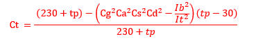
Jon, this is the general formula for voltage drop in BS7671. It applies to cables over 16mm2 where the reactance is tabulated. Candidates on the 2396 are expected to be able to manipulate it appropriately without access to programmes. For cables up to 16mm2 just drop out the + bit at the end.
The Ct value is a correction for temperature and has an advantage where a cable is carrying much less than its design current. It is derived from;
In the Irish Regs, we do not have tables for voltage drop. We have to work out voltage drop from the resistivity of the conductor at operating temperature, knowledge of the load power factor and reactance of the cable. Generally, reactance can be assumed to be 0.08mohms per metre. If you look at say Table 4D4B you will see that 0.08 is approximately half the values given for single phase reactance in column 3 and if you multiply 0.08 by root 3 its not far away from the reactance values in column 4 for 3-phase.
There is no correction factor for cable temperature available as above but I guess it could be applied with justification.
The way set out in IS10101 2020 (Regs in Ireland) for copper is then;
(0.0225 * length/csa * cos theta + 0.00008 * length * sin theta) * Ib
The outcome is then multiplied by 2 for single-phase or by root 3 for 3-phase.
Which ever method you use, you will find that the minimum CSA for voltage drop for the question I posted allows 10mm2. to be used. The question did ask for the minimum value so whilst a basic calculation might indicate 16mm2 or 25mm2, which might pay for itself in the long run in terms of heat loss, the candidate would not get the full marks for that section.
For ccc, assuming overload in starter;
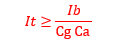
I have Ib at 47.6, Cg at 0.88 (subject to MapJ's point about 30% holes) and Ca at 0.96 which allows 10mm2.
By the way, you can only elect to go for Ib as the numerator where grouped cables are not subject to simultaneous overload if it is the greater of the two options given in equations 3 and 4 in 5.1.2 of appendix 4. It can be used in our case if the protective device is to provide fault protection only.
I went for the easier![]()
As it's below 16mm and the reactive element can be ignored.
My Ib is 28000/1.732/400 plus pf 6.06A giving 46.46A
But went for a more conservative temp correction 4B1 0.91 (40C rather than the lesser 35C @ 0.96)
Either way it suggests a 10mm cable for It.
for a 10mm @ 90C thermosetting cable (4E4B-4) = 4 mV/A/m with 36m and 46.48A is 6.69V drop
for a 10mm @ 70C thermoplastic cable (4D4B-4) = 3.8 mV/A/m with 36m and 46.48A is 6.39 V drop
So a16mm is required for below 6 Volts dropped. (and keep the losses down)
If I do it Lyles way
10mm @ 90C 4 x 0.85 x 40.42 x 36 = 4.9 V drop
10mm @ 70C 3.8 x 0.85 x 40.42 x 36 = 4.7 V drop
10mm OK
If I do it Lyles way
10mm @ 90C 4 x 0.85 x 40.42 x 36 = 4.9 V drop
10mm @ 70C 3.8 x 0.85 x 40.42 x 36 = 4.7 V drop
10mm OK
We're about to take you to the IET registration website. Don't worry though, you'll be sent straight back to the community after completing the registration.
Continue to the IET registration site