This discussion is locked.
You cannot post a reply to this discussion. If you have a question start a new discussion

Arc flash requirements when working in electrical panels ? PPE, arc flash calculations/boundary etc . Struggling to find any information !

Hi everyone, im after some help!

I work for an American company who have a lot of requirements and procedures for determining Arc flash but are all US and OSHA regs and rules. My team work on CNC equipment so our work is mainly live testing on 3 phase and low voltage circuits in panels. I'm trying to determines the UK requirements for Arc flash. I'm needing to know info like Arc flash boundary, how to determine PPE, calculations etc.

Any help would be great !

  • Working dead is the default UK approach in general because of Regulation 14 of the Electricity at Work Regulations 1989, and the use of appropriate test equipment and leads and working practices to help eliminate risk is also a default position in low voltage installations (for example, see HSE Guidance Note GS38, www.hse.gov.uk/.../gs38.htm)

    The IET has published a fact file on arc flash risk management: www.theiet.org/.../

  • There is no easy direct mapping - the approach in the UK, and the EU as well, is not normally based on calculating the type of  PPE needed for some inevitable accident event, but on designing the equipment and operating processes such that at least two, ideally more, things need to fail for an arc flash to occur, so it can be seen as 'unlikely', or ideally 'most unlikely'. So terminals will be shrouded, and live parts hard to touch, even with  access doors open, if testing routinely needs some more exotic instrument connected there will be a suitably shrouded socket for it, and if not the design will  usually be such that a (suitably fused) meter probe has to be pushed in though a hole that will not easily accept anything larger
    Otherwise, apart from Zs and phase rotation, most commissioning tests of insulation and earth  continuity etc can be, and are, performed before the power is applied.
    Setting up of kit that has to be energized to alter motor speeds etc, tends to be restricted to opening up the signals of interest only with the rest remaining at least touch-proof.
    As far as mains supply goes, the permitted disconnection times tend to be faster being based on the potentially higher shock voltages, so the available energy is more limited, and coordination of protective devices and let through energy is normally done first. At the origin you may expect PSSC (Prospective Short Circuit Current )and Zs (the live to earth loop impedance or 'fault loop') to be measured live, but not much else, and that sort of testing involves shrouded probes and care ;-)  this is done from a tester that looks at voltage drops while applying a known load shock L-N or L-E.

    Assuming reports are accurate, arc accidents here are rare and when not builders with excavators and underground cables, often seem to involve older high current equipment belonging to distribution companies that pre-date the post-war world of insulated busbars and interlocked switching, rather than connected machines and so on.  There is still a lot of it about, but it is being slowly phased out. The chaps who pull live company fuses from that kit for a living are supposed to have things like visors and cotton clothing and  suitably rated gloves, but the literature for the examples available tend to be targeted for US use and rated in calories and other historical units so do not map well onto UK design practice.

    Can I ask what sort of live tests are your chaps doing on the CNC kit and how much of it could be re-organised to involve dead tests or connections via say lightly fused test sockets ?
    Mike.

    PS the UK rail network circulates the following advice to its workers.
    Note the use of the comedy units, and complete failure to tie it in with parameters we actually know like PSSC or disconnection time - I'm not blaming network rail - this disconnection in the rare cases you do need PPE is a general problem.

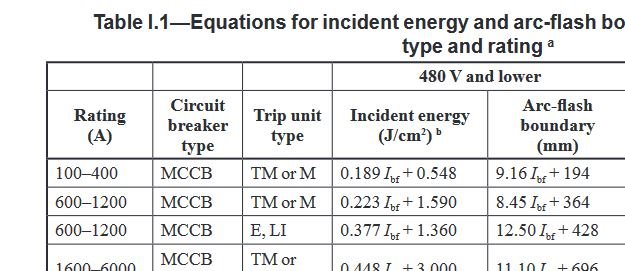
     and for higher power stuff

    Note that in the UK most final circuits below perhaps 100A will be protected by MCB or RCBO.
    IEEE std 1584, that Graham mentions above has an annex I with a section proposing empirical formulae for estimating arc flash energies and distances for breakers - the breaker classifications are not in the right form for UK practice (B/C/ D etc *), but do suggest that a few hundred mm or more will do to get out of the danger zone for trips with near instant action threshold that is lower than 100A. For discussion purposes a small excerpt below. It must also be noted that the formulae for different current bands do not look shaped to join up very well, which is not reassuring.


    Note that in the text it says the  fault current Ibf in that table is in kA,   but this does not seem quite right, if the 400A and 600A results are to look similarly joined up for a given Ibf so there may be some margin of uncertainly, but even so the rate of increase of safety distances with increasing breaker rating is not especially rapid, the PSSC is more important. If not known it is common to assume 16kA at the origin on small (100A or less) services, but it is a common thing to measure on site. And of course it falls quite smartly along a cable run.
    Note the 'current limiting', which is strictly speaking an energy limiting action of an upstream 'death or glory' fuse in such cases can work in your favour, as a reduced value of effective short circuit current can be assumed, as  the fuse will cut things off before the arc has developed its volume of ionized plasma to its full size. However it takes a fair amount of mathematical confidence to be sure of by exactly how much for the purposes of a '1584 style calculation in UK units.

    * Ibf - the 'bolted fault current' is the equivalent of PSSC or perhaps twice the L-N PSSC if you expect a 3 phase (L-L-L) fault so no neutral voltage drop.)
    *The breaker will be rated to break at least this PSSC, and the B type has a near instant trip threshold of five times its nominal load rating, the C type ten times etc.

  • You need a system study to determine the energy at a certain point in your electrical network. So you need to know some details of the protections upstream and internally within your equioment to give an idea of the arc flash energy / duration that then deterimes the calorific value of the PPE required.  Likely all your installations might be similar so you could run a series of small studies using ETAP arc flash module to determine a range of potential arc flash values.  I work in commissioning and things like phase rotation checks nearly always involve live work, but consider if you can use a phase roation meter with crocodile clip probes, connected onto the test locations while the bars are dead, then energised with all personel well out of the way of the probes / meters; that is far safer than (2 people?) leaning into a live panel with point probles, the arc flash risk of live work still exists but the safety barrier is your procedures not the arc rated PPE. Lert  us know how you get on.

    Worth noting that you can reduce the arc flash potential by temporarily droppping the upsteam / incoming fuse or MCB rating, as doubtful lot of fault finding will involve running the machine at full load. Once you are happy the kir is running ok, the last job is to put back in the larger fuse. 

  • May be very worthwhile you checking out my book, the European Arc Flash Guide:  European Arc Flash Guide It will tell you all you need to know. It will be available shortly on the IET Library too.  I have also produced calculators in line with IEEE 1584, fault level, IDMT relays, direct current incident energy, circuit breaker incident energy, German box test calculators, blast and risk assessment forms. These can be found on www.ea-guide.com