This discussion is locked.
You cannot post a reply to this discussion. If you have a question start a new discussion

What consideration should be given while establishing size of CPC in TN-S?

Hello I am looking at some designs provided by external consultants on our site where we have a private 11kV network of substations. Now plenty of our subs are TN-C-S but also we have some mixture of TN-S subs.

Now my question is around sizing a CPC if we would like to convert to TN-S as we have EV chargers being rolled out across site and things would be a lot easier with TN-S in place for earthing arrangement of those chargers in multiple places. Anyway - let's say we have a Sub with a transformer on it sized as 1.25MVA feeding into a 2000Amp ish feeder pillar that feeds into a building via 630Amp fuse. When I size the CPC it comes out as 95mm2 to the feeder pillar and if I compare it to some other buildings those are massive and on some other building with similar parameters it was 300mm2. To be fair for a 2000Amp supply 95mm2 CPC seems a bit low so I have some concerns about the size of this CPC.

My question to you is if I should consider anything else that Amtech considers while calculating CPC between LV Tx side and main incomer on LV? So for instance if I try to achieve selectivity between LV main incomer into the building and HV ring feeder into the transformer? What software would you recommend to use while calculating a CPC on a private network? Many thanks for your help.

  • The thing that traditionally determines CPC size, is the available fault current and how long you think it will flow for before ADS does its thing. ADS is normally fast enough that the adiabatic formula is a reasonable assumption, and the advice in the regs is generally based on this, once you get above sizes that are too small to be mechanically robust. I imagine that the internals of Amtech are simply following the rules.

    For TN-S modern ADS (i.e. fast) allows quite small CPC compared to the main conductors using this method.

    But during a fault, however short lived, there is a voltage division of the supply voltage between resistance of the  line conductor involved and the resistance of the earth return path, and everything sharing that earth return gets pulled up  due to the voltage drop along it- to about half mains voltage near the point of fault, if the two resistances are equal, but rather more than half mains voltage if the earth path resistance is higher than the line. Depending what else  is in the building, and how much the earthing interconnects with other buildings and perhaps with regions fed from other transformers a lower ground bounce ('rise of earth potential') may be desirable. (bonded services, lightning conductors, shared foundations and other bits of metal can all break the assumption that the building is free to bounce on its local earth)
    This is not in the regs, but may have been a consideration, if sensitive loads and high PSSC exist in adjacent buildings.


    aslo on the theme of volt drop are these runs unusually long?

    Of course it may be that non of this applies and the previous installers were just very nervous and wanted to be ready for a supply with any possible characteristic.
    In general if it was correct originally, going from PME to TN-S should relax the requirement, not get harder.
    Mike
    mike

  • aslo on the theme of volt drop are these runs unusually long?

    Thank you for your detailed reply, to answer quoted question no longs are reasonable and everything is within a short distance so no more than 20 meters off transformer into the switchboard. 

    My guess is that it was overengineered and cable doesn't have to be that big (circa half a neutral size).

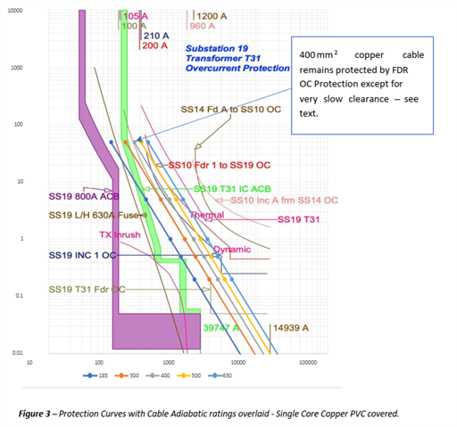
    On another job I had an external consultancy working for a contractor said that CPC needs to be larger than what Amtech shows They overlaid adiabatic ratings of a CPC onto protection curves and stated that Incomer ACB needs to clear a fault in time and that depends on the size of CPC to TX, see picture below, hence the size of it. Surely Amtech should take under consideration clearance time of main incomer ACB on LV side when carrying out the calcs? Which baffles me as on this particular job consultancy advised of 400mm2 CPC to be fitted whereas Amtech was fine with a 95mm2.

  • Ah. Withouot looking at the maths of the situation I wonder if what might be happening is that Amtech is considering the adiabatic on a single design condition (namely a fault of negligible impedance... but do check the program settings for which end of the cable is being thought of), which is what is required by BS7671, while the consultant is considering the full spectrum of faults including high impedance, slow-blowing faults for which the adiabatic equation doesn't hold.

    Are high impedance faults, that don't very quickly develop into low impedance ones, really likely within the zone of protection? Given that this is probably a large, well bonded, metal framed switchboard...

    Of course, downstream faults will have a higher impedance and the CPC at the incomer will need to survive those too. But they should be cleared by closer protection.

    There appears also to be no mention of the HV protection. While for high impedance faults HV OC won't likely help much, depending on the configuration and fault location LV REF might be in play.