60kW 3 x 3phase+N heater unit

Hello,

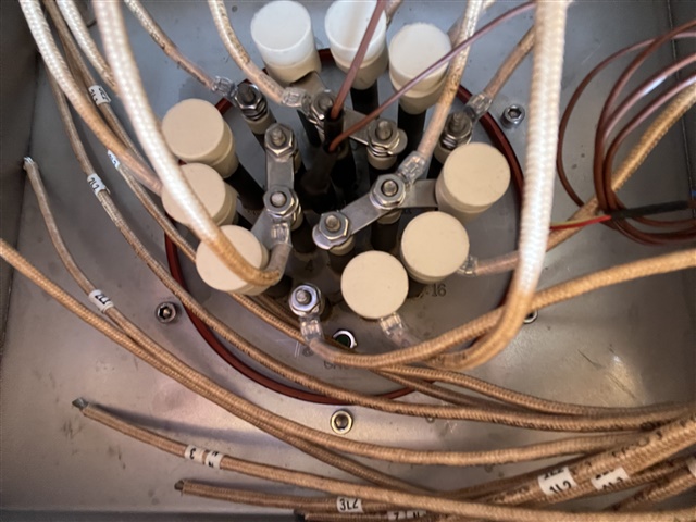
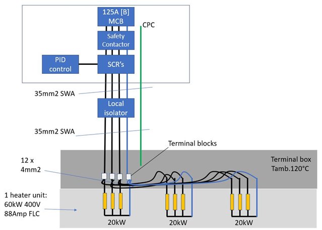
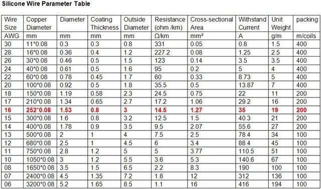
I've a question on the best method of connecting to a 60kW heating unit (picture of terminal box below plus a cartoon of my circuit). I was led to believe this heater was a 60kW star configuration with neutral return and so had anticipated connecting via one supply cable. However, it is in fact 3 separate 20kW heaters (4-wire star configuration), the manufacturer has issued the unit with 12AWG (4mm2) heat-resistant wires from each heater bank and has advised to 'gang' (parrallel) them together.

Anyone have any comments?

I have calculated full load line current at approx 88 Amps. I've selected a 125Amp type B MCB and am using a 35mm2 SWA supply cable. (all checks out ok with BS7671, volt drop, Zs, derating factors eg grouping, ambient etc) I will be installing an isolator close to the heater units and from there (due to this wiring configuration) either use 3 x 5core silicon sheathed (180°C) cables to connect to each of the elements or continue with 4 x 35mm2 as singles in conduit (or 12 x 10mm2 singles) and parallel all 3 heater elements together in its junction box (the lead wires you see aren't long enough to terminate outside of the box and i'm just wondering whether to replace them alltogether with longer singles (180

Im told this is standard practice in the heating industry but in my mind i would have thought the 4mm2 lead wires albeit fairly short (and not big enough in my opinion) aren't adequately protected by the 125Amp breaker anymore, or does this fall under parrallel cabling rules, do they actually need their own branch circuit protection or is it ok to have 3 smaller cables in paralell like this?? 

ANy advice greatly appreciated.

Parents
  • The 'safe' current handling for silicone covered wires is movable feast. If we want to keep the copper below 70C the normal PVC tables apply, but if you do not mind running the copper at 150C or so, then the rating is considerably higher as the attached table shows.

    The chart is based on US wire sizes and the highlighted line is not the 4mm one, but for example shows 35A for a wire of a touch under 1.5mm2 - something we would not normally consider with PVC or XPLE the wire nearest to 4mm2 is rated at 110A. For the wire to be damaged by a fusing event it probably needs to rise considerably higher still.

    Mike.

  • Thanks both for sharing your thoughts.

    so yes my sketch is a little busy and confusing at the bottom of the page  (I was rushing!) 

    I tried to show that I will have 

    3 x heater L1’s connecting to my main supply 35mm2 L1.

    3 x heater L2’s connected to my 35mm2 L2

    3 x heater L3’s connected to my 35mm2 L3

    3x heater N’s. connected to my 35mm2  N

    (And yes, if all 3 elements are equally balanced then 0 Amps in the neutral.) 

    and I’ve had to go to 35mm2 for my main supply cable due to the nature of this particular installation (ambient, grouping etc etc) 

    I have finally had feedback from the heater manufacturer who confirm everything in their terminal box (the photo) needs to be rated to minimum 125C as that’s how hot it can get in there.

    I’m struggling to find suitable connectors. thanks for the link to the ceramic ones but I’ve decided to bite the bullet and replace the existing wires with longer heat resistant wires that I can then terminate in an adjacent terminal box at a much cooler temperature 

    my concerns were based on having 3 sets of heater wires at only 4mm2 where my upstream MCB is rated to protect the 35mm2 supply SWA… I’m effectively creating 3 new circuits with smaller wires. Yes the current in each cable is 1/3rd so I’m not concerned about the wire current rating but nevertheless the MCB is still 125A! I just don’t know if that is good practice? I guess the 4mn2 cables are  very short. I thought maybe I should be putting in additional branch protection eg 3 x 32Amp breakers in the junction box but that seems crazy. 

Reply
  • Thanks both for sharing your thoughts.

    so yes my sketch is a little busy and confusing at the bottom of the page  (I was rushing!) 

    I tried to show that I will have 

    3 x heater L1’s connecting to my main supply 35mm2 L1.

    3 x heater L2’s connected to my 35mm2 L2

    3 x heater L3’s connected to my 35mm2 L3

    3x heater N’s. connected to my 35mm2  N

    (And yes, if all 3 elements are equally balanced then 0 Amps in the neutral.) 

    and I’ve had to go to 35mm2 for my main supply cable due to the nature of this particular installation (ambient, grouping etc etc) 

    I have finally had feedback from the heater manufacturer who confirm everything in their terminal box (the photo) needs to be rated to minimum 125C as that’s how hot it can get in there.

    I’m struggling to find suitable connectors. thanks for the link to the ceramic ones but I’ve decided to bite the bullet and replace the existing wires with longer heat resistant wires that I can then terminate in an adjacent terminal box at a much cooler temperature 

    my concerns were based on having 3 sets of heater wires at only 4mm2 where my upstream MCB is rated to protect the 35mm2 supply SWA… I’m effectively creating 3 new circuits with smaller wires. Yes the current in each cable is 1/3rd so I’m not concerned about the wire current rating but nevertheless the MCB is still 125A! I just don’t know if that is good practice? I guess the 4mn2 cables are  very short. I thought maybe I should be putting in additional branch protection eg 3 x 32Amp breakers in the junction box but that seems crazy. 

Children
No Data