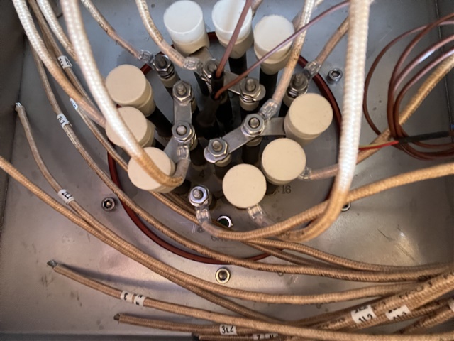
Hello,
I've a question on the best method of connecting to a 60kW heating unit (picture of terminal box below plus a cartoon of my circuit). I was led to believe this heater was a 60kW star configuration with neutral return and so had anticipated connecting via one supply cable. However, it is in fact 3 separate 20kW heaters (4-wire star configuration), the manufacturer has issued the unit with 12AWG (4mm2) heat-resistant wires from each heater bank and has advised to 'gang' (parrallel) them together.
Anyone have any comments?
I have calculated full load line current at approx 88 Amps. I've selected a 125Amp type B MCB and am using a 35mm2 SWA supply cable. (all checks out ok with BS7671, volt drop, Zs, derating factors eg grouping, ambient etc) I will be installing an isolator close to the heater units and from there (due to this wiring configuration) either use 3 x 5core silicon sheathed (180°C) cables to connect to each of the elements or continue with 4 x 35mm2 as singles in conduit (or 12 x 10mm2 singles) and parallel all 3 heater elements together in its junction box (the lead wires you see aren't long enough to terminate outside of the box and i'm just wondering whether to replace them alltogether with longer singles (180
Im told this is standard practice in the heating industry but in my mind i would have thought the 4mm2 lead wires albeit fairly short (and not big enough in my opinion) aren't adequately protected by the 125Amp breaker anymore, or does this fall under parrallel cabling rules, do they actually need their own branch circuit protection or is it ok to have 3 smaller cables in paralell like this??
ANy advice greatly appreciated.
