Bonding to Equipotential Bonding Bar (BS EN 62305) or to Main Earthing Terminal (BS 7671)

Hello,

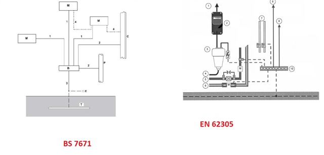
Could the Equipotential Bonding Bar (as it is illustrated in EN 62305-3 fig. Figure E.45) and Main Earthing Terminal (as it is illustrated in BS 7671-2018 fig. 2.1) be the same bar?

Do they need to be arranged as different (separate) and connected bars in installations where we have an external LPS?

In both figures we have the metal installations bonded to these bars, but the names are different.

Also, i don't understand why the minimum dimensions of conductors connecting internal metal installations are different, for example, in the case of copper conductors:

- in EN 62305-3, Table 9 we have 5mm2

-in BS 7671 we have half the cross-sectional area required for the earthing conductor, but not less than 6mm2 (10mm2 for PME conditions).

The minimum dimensions required by BS7671 are always greater, so we should always use them.

This information is very confusing for me.

Thanks in advance for any clarifications. I hope this question is not too naive for this forum.

Parents
  • Lightning systems aren't my area at all, so my thinking might well be out of date (or just plain wrong), but I think I recall diagrams where the bonding from everything else was taken from a single point on the lightning down conductor - to avoid creating unnecessary potential differences within the installation. By comparison if you had a single reasonable length bar, with the lightning air terminal connected at one end and the lightning electrode at the other with a many kA lightning current even a small fraction of an Ohm impedance along the length of the bar could generate a decent voltage difference - a significant fraction of which could then be imposed on different parts of the installation via the other bonding conductors/c.p.c.s.

        - Andy.

Reply
  • Lightning systems aren't my area at all, so my thinking might well be out of date (or just plain wrong), but I think I recall diagrams where the bonding from everything else was taken from a single point on the lightning down conductor - to avoid creating unnecessary potential differences within the installation. By comparison if you had a single reasonable length bar, with the lightning air terminal connected at one end and the lightning electrode at the other with a many kA lightning current even a small fraction of an Ohm impedance along the length of the bar could generate a decent voltage difference - a significant fraction of which could then be imposed on different parts of the installation via the other bonding conductors/c.p.c.s.

        - Andy.

Children
No Data