Adiabatic plots

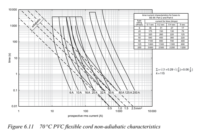
The following copper conductors are plotted in the IET Design Guide;

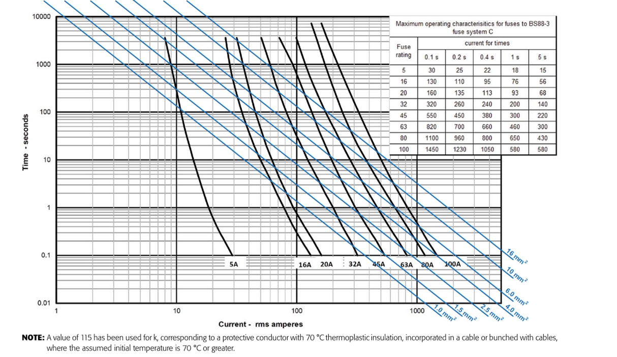
From these, maximum loop impedances have been calculated;

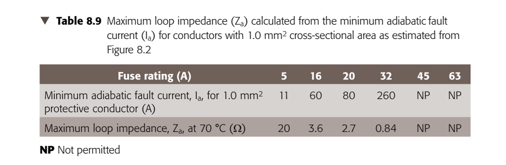
Whilst this is done for a 1mm2 conductor, values can be calculated for other sizes. Surely the adiabatic formula from which the plots have been extrapolated are really only relevant for disconnection times not exceeding 5s. So to say that the maximum loop impedance for a 1mm2 conductor protected by a 5A fuse is 20 ohms is clearly incorrect.

Similarly, a 16mm2 conductor could carry 32A all day long but according to the plot, a 20A fuse would have a maximum loop impedance of 6.8 ohms. 

  • Surely the adiabatic formula from which the plots have been extrapolated are really only relevant for disconnection times not exceeding 5s.

    Yes ... but only in that the formula ignores heat dissipation from the outside of the cable or wiring system.

    So to say that the maximum loop impedance for a 1mm2 conductor protected by a 5A fuse is 20 ohms is clearly incorrect.

    To be pedantic, rather than '20 ohms is clearly incorrect' would be better put '20 ohms is an under-estimate, erring definitely on the side of caution'?

    Non-adiabatic approach according BS 7454 is certainly possible, as referenced by BS 7671 ... this is noted in Section 8.1.1 of the EIDG, but not explored further, at least in the current Edition.

    Using this approach, you'd see that 1.0 sq mm conductors are protected whatever their length, by OCPDs with nominal rating of three times that or more ... which is a good job, because I guess,  , you are coming from the perspective of "Why bother putting 20 ohms related to 11 A in a Table in the EIDG when the tabulated current-carrying capacity of the conductor csa is often more than 11 A that in many conditions of use?"

    What you see when you use this approach is illustrated (although sadly not in colour) on Page 140 of the last Edition of the Commentary on the IET Wiring Regulations (extract below):

  • What you see when you use this approach is illustrated (although sadly not in colour) on Page 140 of the last Edition of the Commentary on the IET Wiring Regulations (extract below):

    Ah! Thank you Graham. 

  • To aid your understanding, consider some additional lines which could be added are vertical ones at the steady state current rating of each of the core sizes, you can then  join them to the blue adiabatic lines for  the same core size, and sketch in a bit of a curve at the intercept. If you do this you can see that the 'it is always 5 seconds'  assumption is also a pretty  poor rule of thumb for sizes that are at the extremes - looking at the intercepts - for 16mm2 it is more like a minute and a half and for 1mm2 perhaps 30 seconds. Perhaps half to a quarter of this time is the "safely adiabatic" limit.

    All of these things (the adiabatic lines and the steady state current ratings) are just comfortable working assumptions, and if you know exactly what you are doing, for short duration loads you can dissipate a lot more without endangering the cable. compared to what the simple rules suggest.

    Actually this is something which we know from experience - for example  2,5mm flex will supply a short shower at 10kw , so long as the person stays under the shower for only  a few mins, and you have to let it cool for at least 4 times that before doing it again. Not that anyone in their right mind would design that of course but it is the sort of silly thing that you find when installations have been extended without too much thought.  In the same way motor inrush etc does not normally do anything to the cable even on motors that take more than 5 seconds to spin up, as these tend to be on the heavier cables. The combined steady state rating and adiabatic curve overlay shows why.

    Mike