Harmonics in 3-phase systems with no neutral

I have an EV charge point that is a 3-phase 4 wire system that comprises of no neutral (L1/L2/L3/PE). As per the datasheet, the third harmonic content of the line current is rated as approx. 8% (THDi ≤8%).


Question: with no neutral, where does the current arising from the third harmonic content of the line current flow? My best guess would be through the protective conductor – which is not ideal as I’m trying to prevent unwanted tripping of the upstream 30mA RCD device.


thanks for the help.

Parents
  • does this depend on how things are connected ?

    It does. Massively.

    The main source of earth currents is RFI filters of designs where the 3 phase lines are decoupled by capacitors wired in star with the star point connected to the incoming supply CPC.

    In most cases the CPC is great for blowing fuses, but too high an impedance at higher frequencies say above a MHz or so, to do much more than function as a long wire antenna that happens to be grounded so far away it does not much affect the radiation of high frequencies from it.

    There is a lot to be said for filter designs that use a delta of RFI capacitors of large value, and then parallel in some smaller ones in star but a lot of the folk in the business do not really understand EMC and tend to do what they did last time to avoid risk.

    left to its own devices the 3 cap star is pretty good, so long as all 3 caps are the same value, and the 3 phase voltages also, as the 50Hz currents then cancel, much as a 3 phase resistive star load needs no neutral.

    Unfortunately when filtering is most needed, the waveforms on the 3 phases are generally not quite the same, and there are high frequency components that are not equal in magnitude or phase and that do not cancel.

    Mike.

  • thanks, Mike

    sorry, it's taken me a while to get my head round this. please let me run this back past you to see if I understand it yet

    a six-pulse rectifier connects the load across each phase pair in turn. this drags a lumpy current down each phase, and we use the convenient fiction of harmonics to describe that lumpiness. triplen load currents don't combine in a common conductor because there isn't one - could we go so far as to say that a six-pulse rectifier is essentially a delta connection?

    is the phenomenon of triplen currents combining in the neutral conductor associated with having many single-phase connections, where each single-phase rectifier connects its load between phase and neutral, so each such rectifier is pushing a lumpy current down the neutral? stretching my earlier point, might we call this a star connection rather than delta?

    There's then another issue of spill current from any filtering where, in the real world, the current through the capacitors won't balance

    how am I doing?

    Dave

  • Absolutely fine, apart from the 'fiction' part - it is no more a fiction than the fiction that my bank balance total is the sum of all the transactions on the account since I opened it ;-) 

    Any repeating waveform really is a sum of multiples of the repetition frequency combined with suitable amplitudes and phases to make up the total at all times. How you deduce those amplitudes and phases, when only given the 'total balance'  time domain information, I defer to our dear departed colleague Mr Fourier, who worked it all out in the margins while the French Army was actually paying him to design a better cannon. (and then in the 1960s Cooley and Tukey wrote a computer program to do it and avoid recalculating the same thing more than once- the FFT - and now the world cannot move anything it seems without a digital signal processor in it somewhere.) Before that  we used 'tuned circuits' to extract the frequency component or components that we wanted, and in the radio world we still do.....

    The problem with 1 phase is as you say - imagine a diode or  bridge of them, feeding a capacitor (or battery). The cap charges on the rising edges to the peak of the AC, and then as the AC drops away, the cap stays full, maybe declining slowly with the load and the AC voltage falls away and reverses. The result is a current that only flows at the wave tops (and bottoms on a bridge) and not in between. As you put it a 'lumpy'  current. So peak current many times the RMS, and flat top voltage waveform as the line voltage drop is time dependent with the current.

     3 of those, one each phase to neutral gives 3 pulses per cycle in the neutral, and as they do not overlap in time they cannot cancel,- result that cable where the copper in the neutral has a funny petrol blue colour and complaints of a hot smell, but no fuses blown....

    Now with the 6 diodes no neutral  it gets a bit more fun - now the current always flows in from one phase (whichever is most positive) and out into whichever one or other of the other two is most negative at that instant in time. And I agree if the world were in perfect balance, then while any one diode would see a lot of 3F, the lines would not. But of course the diodes are not in perfect balance, the line resistances are not in perfect balance, and so maybe more current flows from red to blue on the upstroke than flows from blue to red on the down or something. We may assume that Red to yellow and blue to yellow cancel for now, though generally cancellation will be imperfect.

    and yes caps have a 10% or 20% tolerance over their manufacturing range and further drift with temperature and ageing so that is not perfect either.

    I think you have it, but this sort of mental gym is my bread and butter so I know I can accidentally  leave out the essential 'obvious' steps when explaining, so if things make no sense, do come back and I'll be very happy to have another go.

    ^

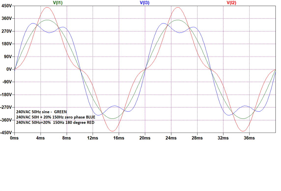
    How 150Hz can give either crest  peaks or flat tops depending on the phase relation of the 3F to the fundamental

    Also note that you could fill in those residual wiggles in the tops with a bit of 9th the right way up ;-)

    Mike.

Reply
  • Absolutely fine, apart from the 'fiction' part - it is no more a fiction than the fiction that my bank balance total is the sum of all the transactions on the account since I opened it ;-) 

    Any repeating waveform really is a sum of multiples of the repetition frequency combined with suitable amplitudes and phases to make up the total at all times. How you deduce those amplitudes and phases, when only given the 'total balance'  time domain information, I defer to our dear departed colleague Mr Fourier, who worked it all out in the margins while the French Army was actually paying him to design a better cannon. (and then in the 1960s Cooley and Tukey wrote a computer program to do it and avoid recalculating the same thing more than once- the FFT - and now the world cannot move anything it seems without a digital signal processor in it somewhere.) Before that  we used 'tuned circuits' to extract the frequency component or components that we wanted, and in the radio world we still do.....

    The problem with 1 phase is as you say - imagine a diode or  bridge of them, feeding a capacitor (or battery). The cap charges on the rising edges to the peak of the AC, and then as the AC drops away, the cap stays full, maybe declining slowly with the load and the AC voltage falls away and reverses. The result is a current that only flows at the wave tops (and bottoms on a bridge) and not in between. As you put it a 'lumpy'  current. So peak current many times the RMS, and flat top voltage waveform as the line voltage drop is time dependent with the current.

     3 of those, one each phase to neutral gives 3 pulses per cycle in the neutral, and as they do not overlap in time they cannot cancel,- result that cable where the copper in the neutral has a funny petrol blue colour and complaints of a hot smell, but no fuses blown....

    Now with the 6 diodes no neutral  it gets a bit more fun - now the current always flows in from one phase (whichever is most positive) and out into whichever one or other of the other two is most negative at that instant in time. And I agree if the world were in perfect balance, then while any one diode would see a lot of 3F, the lines would not. But of course the diodes are not in perfect balance, the line resistances are not in perfect balance, and so maybe more current flows from red to blue on the upstroke than flows from blue to red on the down or something. We may assume that Red to yellow and blue to yellow cancel for now, though generally cancellation will be imperfect.

    and yes caps have a 10% or 20% tolerance over their manufacturing range and further drift with temperature and ageing so that is not perfect either.

    I think you have it, but this sort of mental gym is my bread and butter so I know I can accidentally  leave out the essential 'obvious' steps when explaining, so if things make no sense, do come back and I'll be very happy to have another go.

    ^

    How 150Hz can give either crest  peaks or flat tops depending on the phase relation of the 3F to the fundamental

    Also note that you could fill in those residual wiggles in the tops with a bit of 9th the right way up ;-)

    Mike.

Children
No Data