Harmonics in 3-phase systems with no neutral

I have an EV charge point that is a 3-phase 4 wire system that comprises of no neutral (L1/L2/L3/PE). As per the datasheet, the third harmonic content of the line current is rated as approx. 8% (THDi ≤8%).


Question: with no neutral, where does the current arising from the third harmonic content of the line current flow? My best guess would be through the protective conductor – which is not ideal as I’m trying to prevent unwanted tripping of the upstream 30mA RCD device.


thanks for the help.

Parents
  • One of the nice or nasty things about 150Hz, is that is looks the same on all 3 phases, so if the 3f zero crossing is say 10 degrees after the 50Hz one, on one phase it will also be on the other 2 phases. So if the loads on all 3 phases were exactly equal, the 3 F, 9F components etc would all cancel. However this does not mean that you need a neutral to have distortion to the line waveform that gives a 150Hz repeating feature. In fact the 3 phase/ 6 diode bridge does it depressingly well because in reality the 6 diodes are never quite equal. So the answer is that the 3 F current in any one phase is imperfectly cancelled by the nearly corresponding 3F currents in the other two, and when the 150Hz current is   is 5-10 percent of the 50Hz RMS current then that 3F component is  is 30-20 dB down and is about the sort of thing you get with no special precautions taken.  I would expect any 3F currents flowing in the CPC to be a lot lower.

    Mike.

  • forgive my ignorance, but does this depend on how things are connected, and specifically whether that PE is just a case earth? I imagine that this issue arises all the time with industrial motors and drives, which are generally 3-wire with a PE connection somewhere

  • Hi Mike, Im glad you know a lot about the topic of 150Hz harmonics and how they affect the 3-phase system. You’ve explained how the 3F, 9F, and other odd multiples of 3F harmonics are made by the 3-phase/6-diode bridge and how they’re partly cancelled by the other phases. You’ve also said that the 3F currents in the CPC are likely to be much lower than the line currents. I have a few things to ask and say if you don’t mind:
    • You said that the 150Hz current is 5-10 percent of the 50Hz RMS current, but how did you get that number? Is that a normal or a bad case? How does that change with different kinds and sizes of loads?
    • You said that the 3F component is 30-20 dB down, but what does that mean for the power and voltage distortion? How does that change the power quality and efficiency of the system? How can you measure and reduce this distortion?
    • You said that you’d expect any 3F currents in the CPC to be a lot lower, but how low is low enough? Is there a limit or a rule for how much harmonic currents you can have in the CPC? What are the risks or problems of having too much harmonic currents in the CPC? Cheers

  • What are the risks or problems of having too much harmonic currents in the CPC?

    One of the main risks with any kind of protective conductor current in normal service is the shock risk that can arise if  the c.p.c. develops a continuity fault (i.e. goes open circuit) - anyone touching an exposed-conductive-part connected to the c.p.c upstream of the break and anything else that's still solidly earthed risks that current running through their body. 50mA can easily be fatal - 10mA really isn't desirable and even as little as 0.5mA can be felt - which could be dangerous if the natural reaction to pull back could result in a fall from a height or create some other danger. Normally we try to arrange things so at least two separate faults are needed for normal shock protection to fail, so a single fault in a c.p.c. posing a danger falls below normal standards. BS 761 demands extra precautions be taken if the protective conductor current exceeds 10mA - e.g. duplicate c.p.c.s so that no single fault can cause the danger or larger more physically robust c.p.c.s so the likelihood of an open circuit is much lower.

       - Andy.

  • Thanks Andy. From one Andy to another, I have a good knowledge of the theory and practice of high protective conductor currents and how to comply with the relevant standards and regulations. I'm no expert but do harmonics have A effect of on the impedance of the CPC ? I have read that harmonics can increase the impedance of the CPC, which can affect the fault current and the disconnection time. This can reduce the effectiveness of the protective devices and compromise the safety of the installation. Therefore, it is important to check the impedance of the CPC at different frequencies and ensure that it meets the requirements of BS 7671

  • Sorry for the delay, recovering from a week at Scout camp (not luckily the one in the news just a very wet one with a dozen youngsters in Derbyshire.)

    I'll try and pick your points in order . As always come back if it is unclear or seems wrong - it is quite possible.

    1) You said that the 150Hz current is 5-10 percent of the 50Hz RMS current, but how did you get that number? Is that a normal or a bad case? How does that change with different kinds and sizes of loads?

    As Graham noted the max permissible distortion is set by regulation, in effect as part of the power factor limits, though smaller devices (usually things less than 60 watts) are totally exempt (so some LED lights are terrible which is fine until you have a kW or two of small devices in parallel but any one is below the exemption limit...)

    However I assume your kit is in the power level that  has to meet a standard. Now the harmonic current could be as high a 30% times the power factor, for the worst case sort of kit, but by the time you have 30% of 3f, even with no other contributions the PF is already  below 70%. so the upper bound of any CE marked kit of more than 60W is about 20%. Generally things are a lot better on 3 phase and 5-10% is more like it for things like motor speed controls. Some VFD with active power factor correction are superb 1-2%. The cheap ones less so - they are the 10% end, and maybe a bit higher.

    2) You said that the 3F component is 30-20 dB down, but what does that mean for the power and voltage distortion? How does that change the power quality and efficiency of the system? How can you measure and reduce this distortion?

    a) dBs are a way of measuring power ratios that is logarithmic - which is easier for things like filtering - if you cascade two filters of attenuation  X and Y dB the loss is just (X+ Y) dB. In absolute units like volts or amps the ratios multiply. (so if our XdB was 6dB ==voltage ratio of 50% == power ratio of 4:1 and our YdB was say 20dB, a voltage ratio of 10:1==Power ratio of 100:1 then the combined effect is 26dB, or  a voltage ratio of 20:1, or a power ratio of 400:1) dBs are not magical, but they are convenient, in that a very large range of effects can be expressed with 2 digits and addition is easier than multiplication.

    b) Any  components of the waveform left over after subtracting the wanted 50Hz are the distortion - the 'impurities' if you like - and the total energy in that residue is split among the harmonics- and the levels can be measured by repeated subtraction of the each in turn. Nowadays digitizing a few cycles and letting the computer plot the spectrum. You can buy expensive kit for this but a cheap USB 'sound card' and a transformer to provide isolation are a DIY route.

    Be careful - the % distortion (deviation from pure sine wave) in current and voltage are related by the source and load impedance but generally are not at all equal - if the source impedance is low, the voltage may well be a perfect sine, but the current can be all lumpy..

    c) The sure fire way to reduce harmonic content is with low pass filters, generally series L and shunt C. However, this needs care to avoid resonance effects and the optimum values needed are load dependent.

    You said that you’d expect any 3F currents in the CPC to be a lot lower, but how low is low enough? Is there a limit or a rule for how much harmonic currents you can have in the CPC? What are the risks or problems of having too much harmonic currents in the CPC?

    a) in a 3 phase system I'd expect quite a lot of cancellation - the 3-n currents will flow in the lines,  but in the earth, more or less cancel - the suppression is as good as the balance of the load and source impedance across the 3 phases.

    b) As far as I know there is no enforceable rule of how much of each harmonic over and above the figures in IEC_61000-3-2 and that is the line conductors. However you need to stay below dangerous levels and those that may operate RCD/EL relays.

    c) The risks would be those associated with current in the CPC anyway - namely that if it gets interrupted, then the case of the kit will be tingly live. Very high order harmonics (where the freq is many kHz) do not have the same physiological shock response, so are safer, but in general higher freqs get easier to filter anyway.

    Hope this helps a bit .

    Mike.

  • Hi Mike, thanks for your answer. I’m well chuffed with the amount of info you gave me. It was more than I could have hoped for. I need some more clarification on something if you don't mind? Does the impedance change due to harmonic currents in the CPC, and how does this affect the MCB tripping depending on its type and characteristic, is there a risk of failing to protect against overload or fault currents?

  • Does the impedance change due to harmonic currents in the CPC, and how does this affect the MCB tripping depending on its type and characteristic, is there a risk of failing to protect against overload or fault currents?

    Mike will probably give you a much more accurate answer, but in my head I think of the current as being a mixture of frequencies, each one has its own impedance (1/2πfL etc) so the basic 50Hz fault current flows just like it always does, but the higher frequency components get attenuated in different ways.

      - Andy.

  • The impedance is not a single value at all frequencies - at DC it may be a short circuit, at 50Hz , and at low frequencies a low inductance, but at some frequency the line will be resonant and a very high impedance, and then above t hat  it will look capacitive, Now unless you design trans-continental distribution or railways, at power frequencies this is negligible - you may assume a simple R-L series network for the fault loop. The fact that the harmonics see a different impedance to that seen by  the fundamental means that the waveform changes along the line. 

    It is as if the waveform is split into its  frequency components and each of those components makes its way through the transmission line or inductor /capactitor or whatever at its own speed set by the impedaces  it sees,  in blissful ignorance of the progress or otherwise of the other frequencies. Then at some point you sum the levels of the components that survive that far and recreate the new modified waveform. Clearly each capacitor or wire or inductor only sees the sum of the voltages and current of the various component waveforms that have got that far.

    (the maths chaps and us physics types call this method  "linear superposition", but I suspect that is no help at all, so I'll try not to mention it again....)

    So as a noddy example at one end you put in say 230V of 50Hz and 10V or 150Hz. But the line includes some inductive element so 50Hz sees 1 ohm, and the 150Hz sees 2.5 ohms so the harmonic current is not 1/23 but 1/(2,5*23). At the far end however you have perhaps a 10 ohm resistive load.  So 230-23 = 207 or so volts at 50Hz reach the load, but only 2.5 V or so of 150Hz.

    The high frequencies have been attenuated slightly. In pulse terms any sharp edge has been dulled and there may be overshoot or ringing as well depending on the phase delays between the harmonic components, which I have deliberately not bothered to mention.

    Can harmonics cause ADS to misfire - yes for sure but only in designs near the the edge or where the total harmonic levels are comparable to the fundamental.

    Mike.

  • Yes, harmonics can cause circuit breakers to misfire but also prevent them from tripping. How I see it, when non-linear loads draw current in abrupt pulses, rather than in a smooth sinusoidal manner, harmonic currents flow back into other parts of the power system. Since the peak of the harmonic current is usually higher than normal, circuit breakers may trip prematurely at a low current. If the peak is lower than normal, the breaker may fail to trip when it should. So the original post of "which is not ideal as I’m trying to prevent unwanted tripping of the upstream 30mA" do we agree that this potential dangerous condition if the it's possible the breaker will fail to operate and/or nuisance trip?

  • in principle,  but only with highly non-sinusoidal wave-forms - as you describe the rectifier inrush is a classic for this ,

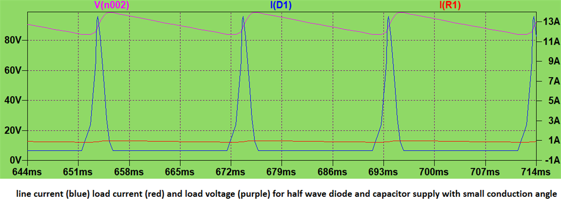
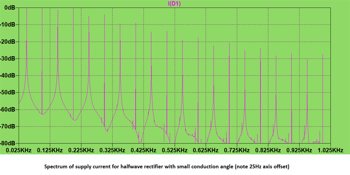
    in a single diode rectifier the 2nd and 4th are at the same strength as carrier,

    Time domain and

    Frequency domain

    And indeed a waveform like this where the 50Hz component is not the dominant can cause premature operation of the breaker, and problems with the neutral in 3 phase by non-overlapping pulses.

    Mike

Reply
  • in principle,  but only with highly non-sinusoidal wave-forms - as you describe the rectifier inrush is a classic for this ,

    in a single diode rectifier the 2nd and 4th are at the same strength as carrier,

    Time domain and

    Frequency domain

    And indeed a waveform like this where the 50Hz component is not the dominant can cause premature operation of the breaker, and problems with the neutral in 3 phase by non-overlapping pulses.

    Mike

Children
No Data