Calculating cables in parallel

Hey guys I've been wondering when your wiring in parrallel do you divide the R1+R2 values by 4 when calculating thermal constraints and checking that the Zs value is okay. 

Also when wiring in parrallel if you only use one of the earth connections would you divide by 3. 

Hope this makes sense. 
Parents
  • Hey guys I've been wondering when your wiring in parrallel do you divide the R1+R2 values by 4 when calculating thermal constraints and checking that the Zs value is okay. 

    No, the (R1+R2) value of each separate cable in the pair is divided by 2, or alternatively if you measure (R1+R2) with the two cables connected together in parallel, you get is the real (R1+R2) value.

    Don't be confused with RFC testing ... r1 and r2 are the end-to-end value along the whole length of the ring (and we use lowercase r). The resistance of each leg of the ring to the furthest point away from the DB is (r1+r2)/2 (half the value of the total ring), and the two legs in parallel therefore give you (r1+r2)/4.

    Don't forget when you are looking at adiabatic, you need to take into account the current down each cable - each cable separately would have to meet adiabatic in case of a fault within the cable itself.

    This highlights a danger in the use of multicore cables in parallel to meet disconnection times if the installation is not managed by a duty holder - if there is a fault in one cable, that blows the fault away, as well as operating the protective device, the protective device could simply be reset, and the circuit re-energized and no-one would be any the wiser. Less likely if the circuit has an RCD (but then, wouldn't that simply provide ADS disconnection times anyway).

    Also when wiring in parrallel if you only use one of the earth connections would you divide by 3. 

    No, just take the one value as R2 ... although if you ware wiring in SWA, the armour would usually be considered to require being part of the earth circuit, as usually it becomes an extraneous-conductive-part when using a gland (and if buried, both cables the SWA would need to be suitable for use as a cpc in its own right, regardless of the use of an internal copper core as supplementary cpc).

  • Are there some example adiabatic calculations for a ring final documented somewhere that explain the use of (r1+r2)/2 ?

    Do you mean (r1+r2)/2, or (R1+R2)/2 ?

    In a ring final circuit, r1 and r2 are the "end-to-end' resistance, so at the furthest point (mid-point) of the ring final, the resistance of each "leg" of the ring is (r1+r2)/2. Because they are in parallel, the effective (R1+R2) at the mid-point is:

    (R1+R2) = (r1+r2)/4

    Section 2.8 and 8.4 of the IET Electrical Installation Design Guide contain an explanation of the process for fuses, but when using circuit-breakers, as is the norm these days, because the disconnection time is so fast, we need to do the adiabatic calculation based on the let-through energy I2t and not using separate I and t from calculation and graphs. This is explained in Section 8.5 of the Electrical Installation Design Guide.

  • I did mean (r1+r2)/2 referring to your earlier reply where you mention the resistance of each leg and accounting for the current down each cable when using adiabatic.

    I'm trying to determine the minimum CPC CSA for an earth fault in a ring final socket circuit with 2.5/1.5 cable and 32A In. It's the impedance to use in the fault current calculation that I'm unclear on. The R1+R2 value results in a high fault current where the CPC CSA is too small whereas if (r1+r2)/2 for a leg is used the CSA becomes acceptable.

  • I'm trying to determine the minimum CPC CSA for an earth fault in a ring final socket circuit with 2.5/1.5 cable and 32A In. It's the impedance to use in the fault current calculation that I'm unclear on. The R1+R2 value results in a high fault current where the CPC CSA is too small whereas if (r1+r2)/2 for a leg is used the CSA becomes acceptable.

    Faults can occur anywhere - if you OPD is an MCB, worst case energy let-though is likely to be with the highest fault current - i.e. for a fault very close to the start of the circuit - so R1.0=0, R2=0.0 and so fault current just based on Zdb. (Yes there are known issues using reduced c.p.c.s with fault currents >> 3kA).

       - Andy.

  • I'm trying to determine the minimum CPC CSA for an earth fault in a ring final socket circuit with 2.5/1.5 cable and 32A In. It's the impedance to use in the fault current calculation that I'm unclear on. The R1+R2 value results in a high fault current where the CPC CSA is too small whereas if (r1+r2)/2 for a leg is used the CSA becomes acceptable.

    As Andy says, what is the prospective fault current at the supply end of the circuit? Typically, if this is under 3 kA, the 1.5 sq mm cpc is generally adequate. To ascertain this, you will need the manufacturer's let-through energy (I2t) for the mcb/RCBO you are using. Assuming copper conductors, you put I2t in the following formula to find a minimum csa (S):

    Smin = {√((I2t)}/115 mm2

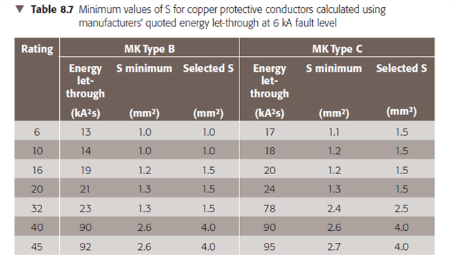
    Let's have a look at part of Table 8.7 of EIDG:

    For a B32 of the particular MK model the data came from, the let-through energy from a 6 kA fault level I2t = 21000 A2s. With copper conductors, k=115, we have:

    Smin = {√21000}/115 = 144.91/115 = 1.26 mm2, so we have to chose a csa of 1.5 mm2 or greater (as csa's come in standard sizes of course).

  • Thanks both for your help. Energy let-through is not an area we have covered in training so I will need to do some more learning.

  • Energy let-through is not an area we have covered in training so I will need to do some more learning.

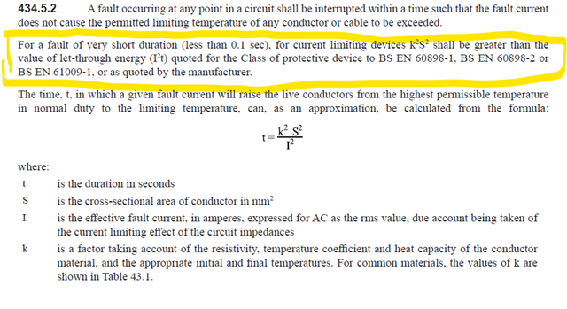
    This is the Regulation in BS 7671 that requires this approach:

    I'm not sure why this is not being taught clearly, because usually to achieve disconnection times according to Chapter 41, circuit-breakers operate in < 0.1 s (it's where the vertical line is on the time-current graphs for circuit-breakers in Appendix 3). There are occasions when the "calculate fault current and operating time" provides a different answer (if you have the correct operating time from manufacturer's data for currents greater than 5In for Type B devices, 10In for Type C and 20In for Type D  ... they not in Appendix 3 to BS 7671).

    It has been a requirement to use energy let-through data in the adiabatic calculation for disconnection times < 0.1 s since 16th Edition (1991) - Regulation 434-03-03 last para for anyone who has a copy of the 16th ed 1991, or BS 7671:1992, to hand.

    In the 15th Edition, it was a recommendation in a NOTE to Regulations 434-6 ... but illustrates it's been part of the Wiring Regs for over 40 years !

  • It's perhaps not always recognised that the even the traditional adiabatic approach is dealing with energy let-through as well. k²S² ≥ I²t is just S ≥ √(I²t)/k rearranged. The only difference is rather than working out I (and hence I²) and t separately and multiplying them together, you get the final I²t number direct from manufacturers data or standards.

      - Andy.

  • and using units of amps squared seconds rather hides the fact that we are really talking about joules  (heating power) per ohm (of resistance in the fault loop) power being I squared R and all that.

    When you know the power and the mass of the metal and its heat capacity tell you the temp rise during the zap. If you know this there is no need for a special formula to remember, you can hit the tarmac running as it were and re-derive it from 1st principles each time you need it, if that is the way you like to operate.

    It also confuses folk when folk bandy about kA2s as to whether the k relates to the amps and should be squared as well (so 1kA2s = million times 1 amp amp second), or to the unit, when it should not. (really it should be the latter and 1kA2s = thousand  times 1 amp amp second, but I have seen it wrong in a few places)

    'Joules per Ohm' and 'kiloJoules per ohm' are clearer ,and explain why things get cooler for a given fault when the cable is fatter and the resistance is lower. (assuming of course that the fault current is set near constant by other impedances not under consideration and not changed by the fatter wire.. )

    Mike.

  • The only difference is rather than working out I (and hence I²) and t separately and multiplying them together, you get the final I²t number direct from manufacturers data or standards.

    Yes, and the important point about that, is the numbers are different from the separate I and t you get from the manufacturer's date on I vs t curves.

  • t also confuses folk when folk bandy about kA2s as to whether the k relates to the amps and should be squared as well (so 1kA2s = million times 1 amp amp second),

    Yes, I understand the argument that doesn't really comply with SI units, but please take it from me, the kilo is not squared, '1 kA2s' means '1000 A2s'. However, this is a comment on product standards and data, rather than BS 7671.

Reply
  • t also confuses folk when folk bandy about kA2s as to whether the k relates to the amps and should be squared as well (so 1kA2s = million times 1 amp amp second),

    Yes, I understand the argument that doesn't really comply with SI units, but please take it from me, the kilo is not squared, '1 kA2s' means '1000 A2s'. However, this is a comment on product standards and data, rather than BS 7671.

Children
No Data