Has my SPD tripped?

I may be being a bit thick, but ...

... how do I know if my SPD is still functioning?

The same might be said of an RCD, but of course we all check them six monthly so we could check the little indicator in the SPD at the same time.

However, if the RCD has tripped, we know about it 'cos the lights go off. If the SPD has exceeded its useful life, we know nothing. The one which I shall be installing at home has a switch for an indicator or buzzer, but that wouldn't be much use for a CU at the back of the hall cupboard/under the stairs/in the garage.

I am left thinking that if SPDs should be fitted, there should also be an effective alarm system. Do you agree?
Parents
  • A further thought ...

    Is there any means of counting the number of surges which have been suppressed?

    The reason why I think of this is that presumably, SPDs can cope with a certain amount of surges (of different intensity) and say, a 95% confidence interval estimated.

    If an SPD has one surge remaining, it doesn't help if a thunderstorm causes two surges. So if the SPD is reaching the end of its life, it should be replaced before it gets there.

    Just a thought whilst I was drilling holes to fix my SPD box ...

  • Sort of, but it is not very practical for the home user.

    Much as you can test a fuse element with a low current or a very short duration high current and measure its resistance, you can do something similar for a an SPD and test it without reducing its life.

    If when new the I/V curve is swept rapidly, so as to reach the breakover voltage - but not to linger there so there is very little dissipation, then if that measurement is re-swept periodically, the degradation of the device with successive 'real' pulses can be tracked as the breakover voltage rises, as the available junction area is reduced by repeated damage and at the same time the leakage current  at voltage below breakdown also rises.

    more on that here www.mdpi.com/.../4018

    However, it is not a simple matter of pulse counts and stopping when one zap from failure - after all right from day one, it is always one zap from failure if the zap is large enough !

    The question is how much reserve do you want over some specific test level....

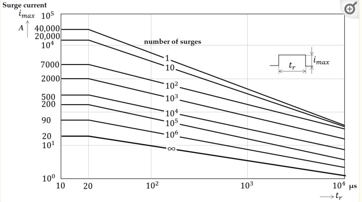
    Data for a real device shows a simple relation where apart from really large pulese - the one to ten pulse cases,  the no. of pulses that constitute 'life' are set by almost the square of the current and the integrated duration - almost our old 'constant energy' friend I2t actually, down to some minimum time, here about 20us, below which shortening the pulse duration does not extend the life by much more, as the current does not have time to spread laterally and be uniform in the crystal, and damage when hot spots form comes into play,

    So, for this device, 100 short pulses of 7kA are comparable to 1000 pulses of ~ 2kA and so on. - and for anything much more than 20usec duration then there is an I2 T limit - which if we look at the 2kA line but now at 100us,  perhaps 2000*2000*100us* 100 pulses or about 40 thousand joules per ohm.

    or take the 1million shots line at about 4 amps and 10 milliseconds - again about 40 thousand joules per ohm..

    This constant let through idea is pretty a reasonable approximation for pulses in the 20us to 1msec range, and in the tens to thousands of amps - really small pulses (the infinity line) do nothing and are the sort of thing used to verify it has not been broken.

    There have been brave attempts to make circuits that sniff off and integrate all the pulses to make a sort of SPD life clock based on this principle, but it is an inexact science.

    The real trick in a normal design is to use an oversized one, relative to the largest surge expected, so you stay below the hundreds to thousands of shots line and expect a long and trouble free life. (not all designs get that last bit right.)

    Mike

    edited for clarity the morning after and to add the I2t example calcs.

  • Mike, thank you - as ever you bring lots of science to the discussion, but (on this occasion) I see what you mean.

  • I seem to recall looking at substations down under that incorporate surge counters. In my head they were CTs around the earth conductor with filters to remove leakage and bounce, but I could be wrong. As such they wouldn't be as sophisticated (i.e. accurate) as some integrating device as described by Mike but I presume that when used in sufficient quantity across a fleet - such as a DNO's network - experience will show that for a specific type of location and spec of SPD it's time to consider scheduling replacement after XX events.

    Quick Google search throws up these:

    www.powerandcables.com/.../

Reply
  • I seem to recall looking at substations down under that incorporate surge counters. In my head they were CTs around the earth conductor with filters to remove leakage and bounce, but I could be wrong. As such they wouldn't be as sophisticated (i.e. accurate) as some integrating device as described by Mike but I presume that when used in sufficient quantity across a fleet - such as a DNO's network - experience will show that for a specific type of location and spec of SPD it's time to consider scheduling replacement after XX events.

    Quick Google search throws up these:

    www.powerandcables.com/.../

Children
  • Thanks for the link, those are really interesting. I like the idea that 'we could not be bothered to give you a primary winding and terminals' becomes a design advantage making it easier for the user - and the primary is then an optional accessory.


    Clearly this is looking for fairly sizable pulses compared to the domestic SPD - the energy just  to fire the counter itself is probably 10-100 millijoules.  (expecting a fraction of a watt for 10 milliseconds or so on the solenoid to operate the ratchet and increment the mechanism, based on ones I have used elsewhere)
    I presume from the sensitivity curve there is some internal diode plus capacitor peak hold/pulse stretcher plus resistive bleed down to generate the clocking voltage. I'm not sure why they chose a 6 digit counter - any pulse that it will survive a million of is no where near worth counting as a significant event...

    Still a fun thing.

    Do you have a feel for the suggested clock count when a replacement is ordered ?

    Mike

  • No worries (c: And indeed the ones I saw were for EHV circuits with devices sat next to a transformer.

    To be fair I'd probably rather route the conductor through a window than have a break in the conductor, given the choice.

    Do you have a feel for the suggested clock count when a replacement is ordered ?

    Not the foggiest, sorry.

    Saw them in situ (not the make/model I linked to) and worked them back to some SLDs I had available to confirm what they were and that was as far as I got; they weren't required on our project (as the supply circuit was short and cabled) so didn't get to dig any further. I'd expect the count action threshold would depend on the sensitivity of the counter, the nature of the line, characteristics of the OVPD etc balanced by risk appetite i.e. network-specific experience. They were installed on the terminations of OHLs for circuits spanning large chunks of the NT in Oz so fairly frequent surges I expect.