protective bonding connection point (TN-S or TN-C)

Question on the correct point to bond extraneous-conductive parts to and what CSA to use for TN-C and TN-S systems
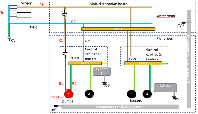
We have two control panels in a plant room supplying a number of different loads (pumps and heaters). Both of the control cabinets have separate supplies and CPC’s (TN-S system) and are supplied from a main distribution switchboard located in a separate room – the main distribution board is on a TN-C  system.

Supplementary bonding isn’t necessarily required for this installation but obviously we want to bond any extraneous-conductive parts so as to keep touch voltages between accessible metalwork below 50V in the event of an earth fault

The control cabinet line conductors are 185sqmm (although the actual CPC’s according to adiabatic and keeping Zs to appropriate values need only be 25sqmm, nevertheless the total Cu equivalent c.s.a. for the Steel armour is about 80sqmm)  

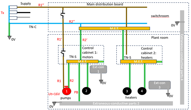
Option 1 : Would you bond the extraneous parts back to the control cabinet MET’s and the control cabinets to each other (they are located next to each other so can be touched at the same time) – BS7671: the protective bonding not less than half required CPC ... so 16sqmm or the maximum being 25sqmm size for TN-S system. 

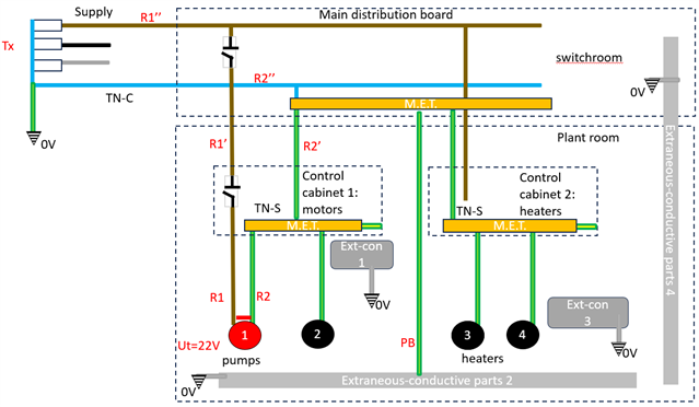
Option 2: Would you bond extraneous conductive parts back to the main distribution board MET with 50sqmm [max size required forTN-C system) as the main dist. Board line conductors are over 150sqmm (I’m not sure if you can apply the adiabatic in this instance??)

Option 3: would you bond extraneous-conductive parts back to the control cabinets with 16 or 25sqmm AND back to the main distribution TN-C system with 50sqmm ?


For me, if it is option 1 then this would result in a lower touch voltage that option 2. but i'm not sure which option is the correct one according to the regs.  And if option 1 then the 50sqmm rule for TN-C systems need not apply and my protective bonding need only be max 25sqmm ?

bonding to the main distribution MET Ut=22V (fine) 
bonding to final control cabinet METs Ut =16V 
Parents
  • so as to keep touch voltages between accessible metalwork below 50V in the event of an earth fault

    There's not a requirement for main bonding to achieve 50V - in many circumstances it's rather unlikely. Even supplementary bonding is only required to limit touch voltages to <50V where the disconnection time exceeds 5s.

    the protective bonding not less than half required CPC

    Main bonding (i.e. to things that can introduce a potential from outside of the overall installation) is to be sized according to the protective conductor size of the installation (or building if an installation spans more than one building and it's not PME) - so the requirement is generally half the size of the building's earthing conductor, rather than half the c.p.c. of some internal circuit. You may use a c.p.c. as part of the connection between the MET and an extraneous-conductive-part if you wish, but it then needs to satisfy the requirements of a main bonding conductor as well as a c.p.c.  (Supplementary bonding sizes can be smaller, related to local circuit c.p.c.s, but then the extraneous-conductive-part would usually have already been main bonded using full size conductors elsewhere).

       - Andy.

Reply
  • so as to keep touch voltages between accessible metalwork below 50V in the event of an earth fault

    There's not a requirement for main bonding to achieve 50V - in many circumstances it's rather unlikely. Even supplementary bonding is only required to limit touch voltages to <50V where the disconnection time exceeds 5s.

    the protective bonding not less than half required CPC

    Main bonding (i.e. to things that can introduce a potential from outside of the overall installation) is to be sized according to the protective conductor size of the installation (or building if an installation spans more than one building and it's not PME) - so the requirement is generally half the size of the building's earthing conductor, rather than half the c.p.c. of some internal circuit. You may use a c.p.c. as part of the connection between the MET and an extraneous-conductive-part if you wish, but it then needs to satisfy the requirements of a main bonding conductor as well as a c.p.c.  (Supplementary bonding sizes can be smaller, related to local circuit c.p.c.s, but then the extraneous-conductive-part would usually have already been main bonded using full size conductors elsewhere).

       - Andy.

Children
  • My misunderstanding, i thought protective bonding was to reduce touch voltages to acceptable levels - that being < 50V.

  • My misunderstanding, i thought protective bonding was to reduce touch voltages to acceptable levels - that being < 50V.

    and a common misunderstanding too!

    In many situations the the voltage at the point of the fault (i.e. on the exposed-conductive-part) can be around half the supply voltage (for TN) (even higher if reduced c.s.a. c.p.c.s are used) - and if R2 is large compared with Ze (as is often the case) main bonding can only make a small improvement in the voltage difference between the exposed- and extraneous-conductive-parts. Even that can be reduced if the exposed-conductive-part itself has a low resistance to Earth or the supply PE elsewhere (e.g. connected to metallic water or gas mains). Hence the emphasis on short disconnection times (0.4s) even within the equipotential zone. While BS 7671 puts requirements on the c.s.a. of main bonding conductors there's no limit on their length - and hence no limit on their impedance - and thus no limit on the voltage that can develop along their length when carrying a given fault current. So main bonding is really a matter of doing the best you can, and anything is better than nothing, but there are no specific guarantees. Main bonding also serves a purpose for shunting diverted N currents around thin c.p.c.s. in PME systems and can sometimes be very effective in TT systems.

    Supplementary bonding is a slightly different kettle of fish in that there is a prescribed impedance that they must be below - which is derived from 50V and the fault current needed to open the protective device within 5s (Ia) - but there's no guarantee that the fault current will actually be that low - on the contrary we're normally careful to ensure that earth fault currents exceed what's needed to open a protective device quickly - and even if we have a rare case where the end of the circuit doesn't meet disconnection times, faults can happen anywhere and a fault closer to the supply will inevitably have a higher fault current. So what happens when the fault current exceeds Ia? Then even with supplementary bonding touch voltages can exceed 50V. So how does that work to prevent fatal shocks? Well in general protective device that take up to 5s to open (i.e. fuses or MCBs, rather than RCDs) open progressively more quickly when the fault current increases. Meeting the 5s requirement for a current that produces 50V normally means you're on a curve that'll disconnect within 0.8s when the current is high enough to produce 120V and 0.4 when it could produce 230V. So it's a kind of hybrid solution that doesn't require disconnection at all when faults currents are low (and the resulting touch voltage ≤50V) but falls back on a kind of sliding scale ADS if the current increases above that.

    In normal situations you don't have to worry about such details, but it can pay to have them in the back of your mind for the occasional weird setup - e.g. if you're relying on time-delay RCDs for ADS with exceptionally long fixed delays.

       - Andy.