protective bonding connection point (TN-S or TN-C)

Question on the correct point to bond extraneous-conductive parts to and what CSA to use for TN-C and TN-S systems

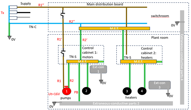
We have two control panels in a plant room supplying a number of different loads (pumps and heaters). Both of the control cabinets have separate supplies and CPC’s (TN-S system) and are supplied from a main distribution switchboard located in a separate room – the main distribution board is on a TN-C  system.

Supplementary bonding isn’t necessarily required for this installation but obviously we want to bond any extraneous-conductive parts so as to keep touch voltages between accessible metalwork below 50V in the event of an earth fault

The control cabinet line conductors are 185sqmm (although the actual CPC’s according to adiabatic and keeping Zs to appropriate values need only be 25sqmm, nevertheless the total Cu equivalent c.s.a. for the Steel armour is about 80sqmm)  

Option 1 : Would you bond the extraneous parts back to the control cabinet MET’s and the control cabinets to each other (they are located next to each other so can be touched at the same time) – BS7671: the protective bonding not less than half required CPC ... so 16sqmm or the maximum being 25sqmm size for TN-S system. 

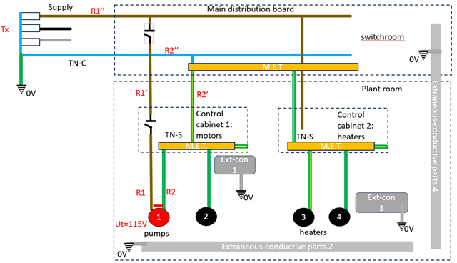
Option 2: Would you bond extraneous conductive parts back to the main distribution board MET with 50sqmm [max size required forTN-C system) as the main dist. Board line conductors are over 150sqmm (I’m not sure if you can apply the adiabatic in this instance??)

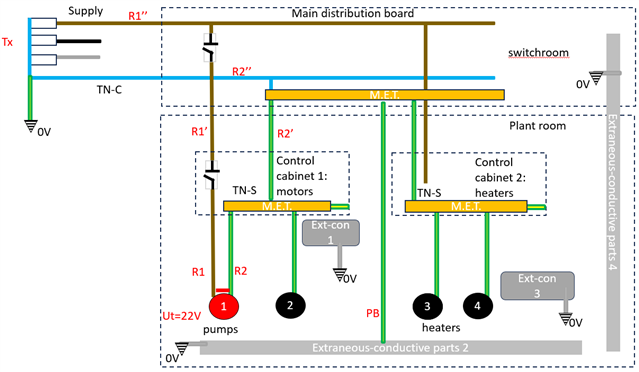
Option 3: would you bond extraneous-conductive parts back to the control cabinets with 16 or 25sqmm AND back to the main distribution TN-C system with 50sqmm ?


For me, if it is option 1 then this would result in a lower touch voltage that option 2. but i'm not sure which option is the correct one according to the regs.  And if option 1 then the 50sqmm rule for TN-C systems need not apply and my protective bonding need only be max 25sqmm ?

bonding to the main distribution MET Ut=22V (fine) 

bonding to final control cabinet METs Ut =16V 

Parents
  • so the only conclusion is each building has its own MET.

    I can see that from the point of view of 411.3.1.2, but then wording of 542.4.1 and the very definition of an Earthing Conductor seem still to be in the era of one MET per installation. I guess it all fitted together rather more neatly going back 4 or 5 editions when each building was considered to have its own installation (with its own DP isolation). Sometimes it is useful to be able to distinguish a building's earth terminal from an installation's (despite the recent changes to 544.1.1).

       - Andy.

  • but then wording of 542.4.1 and the very definition of an Earthing Conductor seem still to be in the era of one MET per installation.

    I'm not 100 % with that. I can see that 542.4.1 requires at least one MET to connect the earthing conductor an an installation that has earthing of any description (most installations). That doesn't preclude other METs being provided. The definition of earthing conductor doesn't preclude other earthing conductors (to other earth electrodes, per the definition of earthing conductor ... but they could be for FE as well as PE and they are required to also be connected to an MET).

    542.4.1 would certainly require an MET in each building having any of the following not connected to an MET elsewhere in the installation:

    • cpc's in the case of TT or IT systems with independent earth electrode for that building.
    • extraneous-conductive-parts
    • FE conductors
    • LPS

    You could also take the view that the cpc of an incoming distribution circuit to a building provides the means of earthing for that building (where connected), and therefore that wouldn't preclude an MET in a separate building supplied from another building having an MET if only for connection of cpc's per 542.4.1 (i)

  • Can you have a branching earthing conductor?

    If the CPCs are all inserted into the earthing bar in a DB, and all the bonding is inserted into a terminal strip which is outside the DB, which is the MET? (542.4.1)

  • Can you have a branching earthing conductor?

    Not sure it's an earthing conductor as defined in BS 7671

    If the CPCs are all inserted into the earthing bar in a DB, and all the bonding is inserted into a terminal strip which is outside the DB, which is the MET? (542.4.1)

    It could be considered (say in a domestic installation) that the conductor you're talking about is the cpc associated with the tails for that distribution board?

    It then connects the other cpc's back to the MET.

    All arbitrary really ...

Reply
  • Can you have a branching earthing conductor?

    Not sure it's an earthing conductor as defined in BS 7671

    If the CPCs are all inserted into the earthing bar in a DB, and all the bonding is inserted into a terminal strip which is outside the DB, which is the MET? (542.4.1)

    It could be considered (say in a domestic installation) that the conductor you're talking about is the cpc associated with the tails for that distribution board?

    It then connects the other cpc's back to the MET.

    All arbitrary really ...

Children
  • "Arbitrary" sums it up nicely.

    In my old supply, the PILC is connected to a terminal bar (the MET??) by some 4 rather weedy looking bare copper wires (I have checked and they are 4 mm² each) in the meter cabinet. From there, a bit of green and yellow goes to a switch-fuse in an adjacent cabinet. The downstream side continues under the breakfast room floor where 3 cores of a 5 core SWA are used. The CPC  terminates in a strip adjacent to the first DB where it is joined by umpteen bonding conductors (and a short CPC to the board). So is that the MET or BET or BMET? It would never have made sense to take all the bonding under the floor to one of the external cabinets.

    The Lucy service head of my new supply has 2 earth terminals. 2 terminals = 2 earthing conductors!

    So I think that we can forgive the OP for having 3 METs.