A normal installation

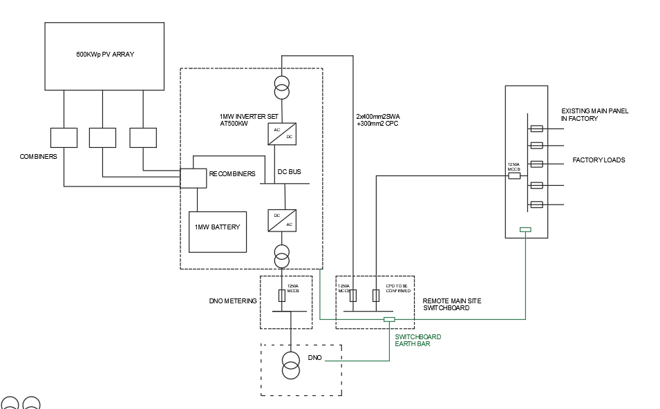
I guess I am going to need to recognise that the relatively simple electrical installations with just a DNO source and perhaps a back up genny that  I have been used to will become an increasingly distant memory. Perhaps for some, the diagram below is meat and potatoes but for me wrestling with it in a practical way on site during a periodic inspection is not an easy task. Last time I was on this site, around five years ago, the DNO supply and metering were directly connected to the main switchboard at the lower right hand side of the diagram. Now re-directed into a metering cabinet and then to a loose arrangement of plant tightly packed which also includes the 1MW battery. 

Establishing Ze and Ipf is a tad more convoluted! I assume the output transformer is referenced to earth and uses the DNO earth for that purpose.  

Parents
  • That sort of installation is by no means confined to industry. Do you have two Ze: i.e. one for the DNO supply and another for the PV array + battery?

    The installation shown seems to combine the DNO and PV supplies before the main switchboard, but what if they are parallel supplies, both of which feed the switchboard. Even more complicated, what if the PV array is connected more peripherally? I visualise the electrons from both supplies competing to supply the loads.

Reply
  • That sort of installation is by no means confined to industry. Do you have two Ze: i.e. one for the DNO supply and another for the PV array + battery?

    The installation shown seems to combine the DNO and PV supplies before the main switchboard, but what if they are parallel supplies, both of which feed the switchboard. Even more complicated, what if the PV array is connected more peripherally? I visualise the electrons from both supplies competing to supply the loads.

Children
  • In this type of installation, Ze  and Ipf are not something you can measure, but have to determine by other means ... quite simply because the inverters operate in such a way, that test equipment to BS EN 61557 series can't identify the true contribution of the inverter (in either connected mode or island mode).

    Guidance on how to deal with this is provided in a number of IET publications, including the latest GN3, CoP for Grid-Connected Solar PV Systems, and CoP for Electrical Energy Storage Systems

  • I read both of the latter two while on holiday. Heavy going somewhat mollified by the occasional tipple! Perhaps because of the tipple I didnt really see where in the texts the explanations on how Ipf and Ze were established. 

    Might it be reasonable to use the data for the transformer nearest the load and the impedance of the interconnecting cables as if it were directly grid connected? 

  • Perhaps because of the tipple I didnt really see where in the texts the explanations on how Ipf and Ze were established
    • GN 3, 98th Ed: Section 2.6.24 (page 107).
    • Solar PV CoP, 2nd Ed: Section 16.5.3 (pages 175-176)
    • EESS CoP, 2nd Ed, Section 12.2.2 (page 119)

    In particular type of installation shown in the OP, it's rather different to the "connected mode vs island mode" type approach, as the installation runs through an inverter at all times, meaning it would be necessary to establish Ipf (tx primary) as the maximum output of the inverter set (before current limit) and then use that, with the transformer characteristics, to establish Ipf on the LV side of the transformer ... which can then be used to determine Ze for a TN-S system.

    As a 'rule of thumb' the current limit of an inverter is typically 1.2 times the rated output current; however, it is recommended the manufacturer's data is used.

    The "missing link" regards Ze for an inverter in a smaller installation, is that the internal resistance may be required to be taken into account - this can only be as declared by the manufacturer.

  • Thank you Graham. Yes, I did read those references, I think they are mostly the same. However, as you rightly pointed out they didnt answer my query with respect to the situation I described in the OP where the installation is supplied at all times through a 1MW inverter.

    Anyway, even without inverters, the measurement of Ze and Ipf are in fruit machine territory when the installation intake is a few metres from a 1MVA Tx . Using R1+R2 on 400mm2 cables in parallel would be of little use in assessing the real impedance to assess Zs at the remote LV switchboard. Patching in the other variables is likely to result in a far from accurate assessment when we have three transformers and two converter/inverters to contend with. 

    As I understand it, the architecture was the outcome of the NIE not permitting the relatively large PV array to be grid connected. Unless there are other ways to satisfy them, there is likely to be an increase in this type of arrangement, which is why I would like to have these fundamental issues made clear. 

    Further, there doesnt seem to be any real movement on the academic side of things with prosumer installations, just an occasional glib mention on the 2391 and 2396. 

    I would like to bring a thoroughly well-worked example into the next  2396 in September, even if it is just for academic interest.