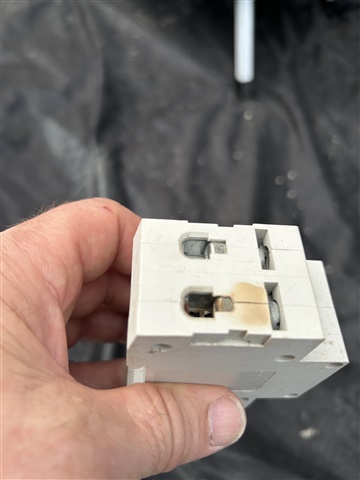
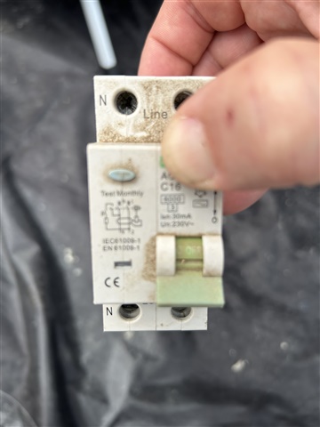
Caravan Site - Overheating supply neutral connection on pitch RCDs

Hi,

Am presently staying at a farm caravan park in south of England and the owner has shown me a problem he is having with some individual pitch electrical devices. Apparently, over time a number of the Type C  16A RCD devices have been affect by the INCOMING supply neutral connection overheating. Seems unlikely to be loose connection on so many devices and device are not tripping. 
site is served by overhead 2 phase connection with single phase distribution to at least 3 sepeate areas built at different times. Pitches are served by buried SWA and marked up as “ring”. RCDs are British supplier and all other connections on the 30mA device are clean and unaffected. Are we looking at an harmonics problem or distribution system fault. All suggestions welcome (It won’t spoil my holiday) Thanks

Dave


Parents
  • Hi DMB, probably loose connection but just a thought. Are the pitch sockets connected by actual ring final circuit? Maybe this is a bit out there, but due to the earth rods etc of the pitches there could be a potential difference between these rods/plates buried in the ground. This could make a circulating current in the ring circuit that could also make the neutral connection of the RCDs too hot. The circulating current is a current that goes around in a circle inside a circuit without going through the RCD. 

  • but due to the earth rods etc of the pitches there could be a potential difference between these rods/plates buried in the ground. This could make a circulating current in the ring circuit that could also make the neutral connection of the RCDs too hot.

    not sure I have understood you, I may have the wrong image of your idea or it sounds a bit unlikely to me. Currents in the CPC will not affect the RCDs - it does not even go through them, and the only neutral - earth bond will be at the site transformer or main incomer - on the load side the only time earth ever meets either neutral or live is during a fault, and the RCD fires some tens of milliseconds after.


    However, burnt neutrals really are a thing and really seem to be more common than burnt phases even on single phase parts - cooker switches, shower switches you name it, only this week I was greeted  by a colleague holding some burn out floortrack (the kind that is a bus system to boxes with 13A sockets) with guess what, a burnt neutral, and we shook our heads and both agreed we saw more cooked  N than cooked L. Perhaps makers just cheap out on the neutral terminals or the live side is more likely to self clean and sizzle and then spot weld back to a low resistance state for the same degree of corrosion or whatever ??

    If you do drill the rivets and open it onto a table, post pix if you can - post mortem are always interesting.
    Mike.

  • I appreciate your expertise, but I have a question regarding a possible scenario. What if there is an existing neutral-to-earth fault on the supply ring main, which may not require RCD protection? Could the potential difference between the earth rods then increase the current in the neutral incoming terminal?

  • To be more specific, I am referring to a neutral-to-earth fault on the supply side ring circuit that connects each RCD, not on the load side. Such a fault would not cause an MCB to trip, as you explained.

  • But by definition, the current on the L path through the RCD and the current through the N path can't differ by more than 30mA, or the RCD would have tripped. It doesn't matter what arrangements or faults there are upstream of the RCD. Only if there was a a N-E fault just upstream of the RCD (as in mm or inches) which caused a fault current of many amps to flow (which seems unlikely) could the upstream N get cooked and some of that extra heat get conducted to the N terminal. All seems a bit unlikely.

  • I am referring to the current in the neutral wire of the ring circuit that supplies power to the RCDs, not the current that goes through the RCDs. Also, the earth rods of different pitches may have different voltages between them because of various factors. So, could this make the current in the neutral  of the ring circuit higher?

  • I may have misunderstood the setup, but is it not a ring circuit that supplies power to multiple RCDs? And have they not had several RCDs fail on the supply side only? Is it not the current in the neutral wire that goes around from the distribution board through all the neutral terminals on the line side? The current in the neutral wire can still be balanced through each RCD.

  • What is the rating of the protective device and what is the max demand? If the circuit is on a 40 A breaker, there could be a risk of overloading a 16 A terminal if the load on that terminal exceeds its rating. This could cause overheating and damage to the terminal and its connections.

  • Hmm if the supply terminals each held 2 wires, a loop in and a loop out as part of that ring, then the terminal may be overloaded. But that probably applies the same to the live path and I thought from the description it was more of a ring with spurs.

    Is it ? How many wires in each terminal ?

    Mike.

  • Hi DMB, probably loose connection but just a thought. Are the pitch sockets connected by actual ring final circuit? Maybe this is a bit out there, but due to the earth rods etc of the pitches there could be a potential difference between these rods/plates buried in the ground. This could make a circulating current in the ring circuit that could also make the neutral connection of the RCDs too hot. The circulating current is a current that goes around in a circle inside a circuit without going through the RCD. 

    A few things make that difficult...

    Firstly each electrode will have a significant resistance around it (due to soil being a less than ideal conductor) - even in relatively conductive damp soil you'd likely be looking a several tens of Ohms for a normal 4' rod. So even if you had a very significant voltage difference - 20V or 30V say, you'd likely have less than an amp flowing - unlikely to be significant for overheating if the joint is otherwise sound.

    Then there's how to get that current to flow along the N conductor(s) in the ring - getting the current to circulate around the entire ring would be tricky - you'd likely need some very odd combination of faults to get the c.p.c/armour and ring N to act as some kind of 1-turn transformer, especially if you wanted to get any significant current transferred (normally, being a ring, things would tend to cancel out). A N-c.p.c. short is maybe more likely - in which case the extra current would likely divide between the two legs of the ring (although not necessarily equally) - but as it was a small current to start and it's only going to get smaller.

    Then how does that extra current flowing in the ring N get to overheat the RCBO terminal - clearly if it's on a spur it's not going to happen, so next most likely is that the ring N is looped into the RCBO's incoming N terminal - but in that case - as it's a single hole terminal - most of the current will flow direct from one wire to the other (the terminal just physically holding the two wire ends together - in the manner of a screwit) - only a small proportion will have to flow around the terminal itself - so again starting an extra amp or so the effect on the terminal is going to be very small indeed.

    There may be other possibilities - e.g. supply N being at an unusually high voltage (e.g. due to a network fault (broken PEN) or an uncleared L-earth fault in another TT installation), which together with a N-PE fault could cause currents to flow in N conductors where they shouldn't (in PME systems which have bonding to extraneous-conductive-parts that themselves have a low impedance back to the source, such currents can be substantial) - but again in this situation we have the limiting effect of the electrode resistance. In such cases the likely complaint is much more likely to be tingles/shocks from electrical metalwork than burned out terminals.

       - Andy.

  • “If the circuit is protected by a 40 A breaker, there is a risk of overloading a 16 A terminal if the load on that terminal exceeds its rating” The location of the overload in the ring main depends on the position of the RCD on the circuit and the length of leg A and leg B of the ring. The current in each leg varies depending on these factors. When the RCD is closer to the consumer unit, the current in both legs is higher. When it is farther from the consumer unit, one leg has lower current and the other has higher current.

Reply
  • “If the circuit is protected by a 40 A breaker, there is a risk of overloading a 16 A terminal if the load on that terminal exceeds its rating” The location of the overload in the ring main depends on the position of the RCD on the circuit and the length of leg A and leg B of the ring. The current in each leg varies depending on these factors. When the RCD is closer to the consumer unit, the current in both legs is higher. When it is farther from the consumer unit, one leg has lower current and the other has higher current.

Children
  • Imagine a scenario where there are three sockets on a 50m2 ring main. Each socket has a load of 16 Amp. Socket 1 is positioned 5 metres from the consumer unit, socket 2 is 15 metres and socket 3 is 25 metres away. Leg A at socket 1 is 14.4 Amps, leg B is 1.6 amps. Leg A at socket 2 is 10.5 amps, leg B is 5.5 amps. Leg A at socket 3 is 8 amps, leg B is 8 amps. Therefore, the total current on leg A is 32.9 amps and on leg B is 15.1 amps. It seems that the terminals of a 16 amp device could be overloaded in this case.

  • Yeah, but that doesn't explain why only the N has burnt out. Any such overload would be very similar on both the L and N legs of the ring.

  • The neutral pole is many times the first suspect also on a shower pull switch if your shower draws more current than the switch can handle. What are your thoughts? 

  • It seems that the terminals of a 16 amp device could be overloaded in this case.

    No, because the terminal is not drawing more than 16 A. The CSA of the cables in the terminal is double the cables in the ring.

  • We have have discussed this in here previously. If the switch is 2-pole and the terminals are the same size (why would they not be) how can one run hotter than the other?

  • Let’s wait and see what DMB concludes. 

  • Remember that effective communication is a two-way street, and it’s important to listen to others’ perspectives as well as expressing your own. Instead of saying “no,” you could try saying “I disagree” or “I see things differently.” This can help keep the conversation constructive and productive. I hope this helps.

  • I hope this helps.

    No.

  • The neutral pole is many times the first suspect also on a shower pull switch if your shower draws more current than the switch can handle. What are your thoughts? 

    There have been several discussions on that very subject (and not just on overloads). Several theories abound, but my favourite is that shower pull switches (especially the types with terminals on the "faceplate") are very easy to create loose connections (as large stiff conductors, typically held by a small single screw attempt to twist as they're pushed back into the backbox) - that should happen equally with L and N of course, but then a loop test (or R1+R2) is done - so loose connections on L are much more likely to be spotted and therefore corrected; while on the other hand none of the standard tests check N continuity, so loose connections there are much more likely to go into service.

       - Andy.

  • shower pull switch

    I am asumming that it is located in the room of the shower and thus is exposed to high humidty and ingress when the shower is in operation.  What IP rating does the shower pull switch have other than a very basic IP2x ?