Leakage current in earthing system due to transformer neutral (star point) directly connected to Power distribution panel.

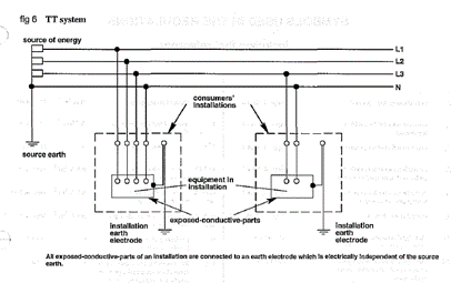
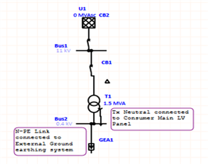
In one of the new project, the neutral of the transformer (star point) is directly connected to the main distribution panel board's neutral bar. Instead of connecting the transformer neutral directly to the ground earth electrode, this neutral bar is linked to the earth bar of the same LV Panel and then the earth bar is connected to the external earth electrode. The transformer neutral must be solidly earthed, per BS 7671.

Leakage current was discovered in the distribution system's earth line during testing and comissioning. Thank you for any and all explations regarding the possibility of the leakage current in the ground cables.

Parents
  • The source earthing arrangement sounds like PNB - a version of TN-S where in effect the transformer tails extend to the first panel. Not an uncommon arrangement at all with private transformers.  BS 7671 doesn't specify actual distances between the windings and the N-PE link so such arrangements aren't in contravention. Earthing the neutral some distance away from the transformer isn't that uncommon even on pubic supplies - often seen on pole mounted transformers with separate HV and LV earthing systems - the LV earth is often connected to N one overhead line span away from the transformer (on both PNB and PME arrangements).

    Any leakage will likely be due to other causes (anything from imperfect insulation to supplying equipment with high protective-conductor-current, to external differences in potential imposed across the earthing system.

       - Andy.

  • Thank you Andy for your quick response.  The project referred is having TT System. The below earthing system configuration is repreduced from BS7671.

  • Some current in or out of the electrode should not be a concern in normal operation but it should be small compared to the normal load currents.

    How big is the transformer (few kVA... many MVA.. ) how much leakage are you seeing mA ...A .. kA (!)

    Expected leakage from loads with a lot of capacitors in to be no more than 1% of full load current and more general resistive and motor loads to be probably no more than 0.1% (so one amp per kA) The unloaded transformer itself should manage below the 0.1% mark as well.

    Does the transformer core, box  and mountings have their own HV earth electrode isolated from the LV earth, or is it sharing electrodes with the secondary ? Normally we only share if the electrode resistances are very small (An ohm or  less perhaps) as we do not want to couple any HV side fault currents into the LV network.

    Is this current you report measured with loads connected or is it unchanged  when the outbound wiring is disconnected? If amps are involved you may have an extra NE bond or even a phase to earth fault in the load side you have not yet realised.

    At the risk of telling you something you already know, take great care not to accidentally open the main earthing path while the transformer primary is live. If you end up in series with even a small earth current it may well be the last thing you do. So clamp meters only please and keep the big spanners in the  box...

    Mike.

  • A rather noddy 'single line' view of a  LV/HV transformer where HV and LV line to core capacitance and winding to winding capacitance effects have been separated out.
    There is no actual capacitor with leads in there of course, this circuit model just represents the energy stored in the unavoidable electric fields around the various conductors and the degree by which they overlap.
    For a 1MVA tx, if you have no makers data, assume something between 1 and 15 nanofarads for CH and CHL, and about 1.5 times that for CL, scale more or less proportional to KVA.

    What you do not want is to absent-mindedly unbolt  a mounting bolt or bracket and put yourself in series with CH... even a 6kV line (UK standard HV at 11kV phase to phase is ~ 6kV to ground) in series with a capacitor of a few nanofarads will  pass enough current to kill. (each nF at 50Hz is pi megohms, so several 10s of mA are possible)
    (and yes the currents from 3 phases will cancel to quite a degree, but only if the inter-winding capacitance == winding geometry ) is perfectly balanced. On an standard in-line 3 leg core it isn't as the centre and end legs are very different.


    Mike.

    Edited for typos and clarity.

  • Hi Mike, Thank you for the information. The transformer is 1500kVA, 400V/230V/50Hz. Delta/Star. There are more transformers connected in the same configuration independently with sharing LV Earthing system.

    The leakage current noticed in the earth cable was varying 100 to 300mA when load is connected. We did not come across any fault in the system during the test.

    There are UPS with capacitors in the project also VFDs.

    The load on the transformer is in unbalanced state.

    Transformer core /body is having combined earth with LV. There is no separate HV Earth.

    The external ground earth is combined (sharing) and is a ring system (<1 ohm).

    Your advise is very valid, we use only clamp meters and not opened the earth path.

    Hope the above information is helpful.

  • Ah well a 1500KVA TX is not a small animal, it is quite a beast- near enough 2000 amps per phase  (as you have loadside 230V/400V 3 phase and not some exotic special voltage), and if you have VFD loads as well then to lose what is really a very small fraction, and into an earth that is not going to blink in terms of voltage bounce, should be no cause for alarm - indeed it sounds like more or less business as usual. Perhaps make a note of the numbers measured in case it suddenly rises at some future inspection, as that could be a helpful early warning of trouble.

    Mike.

  • Hi Mike, Thank you for the information. The transformer is 1500kVA, 11kV/400V/50Hz. There are more transformers connected in the same configuration with sharing LV Earthing system.

    The leakage current noticed in the earth cable was varying 100 to 300mA when load is connected. We did not come across any fault in the system during the test.

    There are UPS with capacitors in the project also VFDs.

    The load on the transformer is in unbalanced state.

    Transformer core /body is having combined earth with LV. There is no separate HV Earth.

    The external ground earth is combined (sharing) and is a ring system (<1 ohm).

    Your advice is very valid, we use only clamp meters and not opened the earth path.

    Hope the above information is helpful.

  • I think our messages have crossed in the post and got out of sequence ;-)

    Mike.

  • The project referred is having TT System.

    I'm slightly confused now. Where's the 2nd electrode come into this and are you suggesting the N-PE link in the main panel is on the "source" rather than "consumer" side of things?

    The leakage current noticed in the earth cable was varying 100 to 300mA

    That does seem pretty small to me - it's not uncommon to see >30mA from small (<100A) installations, so for a system of your side several amps wouldn't be unexpected.

       - Andy.

  • Hi Andy, thank you for sharing your Views. Your question on N-PE link, please see the attached sketch showing the power system impedance diagram for more clarity.

Reply Children
  • thanks - I still can't see anything there to suggest it's TT though - are you sure it's not TN? (TN-S would be much simpler and more usual with private transformers).

       - Andy.

  • I appreciate your observation, Andy. I simply want to express my opinion regarding the earth leakage current. Since the project load distribution is unbalanced due to the majority of the connected load being idle and not in use, is this the source of the earth leakage current? As a result, three phase load balancing is impossible. There will be an unbalanced current in the transformer neutral due to the unbalanced load on the transformer. The N-PE connection in the Main LV Panel will be a path for circuiting the imbalanced current to earth even if it is connected to the ground earthing system since the transformer neutral is not directly earthed to the ground electrode and is instead connected to the distribution board neutral. The ground earthing system is connected to the N-PE link  of all distribution panels by a ring earthing system in the project.

  • Sounds to me like there's a number of different things potentially going on here.

    Protective conductor currents - i.e. the "leakage" from filters and the like on electronic equipment) will occur just the same whatever the load or earthing arrangements (presuming things are earthed) - unbalanced 3 phase loads don't really make much difference to how protective conductor currents occur from single phase equipment, although where the protective conductor currents are in phase with the load currents, there will be a tendency for them to cancel out much more locally to the loads (e.g. at a local DB earth bar if several single phase loads are fed from difference phases). Typically we're talking milliamps per load.

    Different arrangements of earthing the N don't make any difference protective-conductor-currents (i.e. leakage from individual loads) but  some arrangements - typically TN-C-S where a protective conductor also carries neutral currents (i.e a PEN conductor) can result in a portion of the neutral current flowing in what conventionally is considered to be the earthing system - usually referred to as diverted neutral currents. In a sound system that can only happen where the N is earthed at two or more points (creating a PEN conductor) - in conventional TN-S (and indeed TT) systems N is earthed a single point only, with N otherwise insulated throughout, so there's no route for neutral current to circulate via the earthing system. Where a PEN conductor is involved, the N current will divide between the conductor and parallel paths provided by the earthing system according to the relative impedances - if the parallel path is all metallic then a significant proportion of the N current is going to be diverted - so we're often talking a very significant number of amps.

      - Andy.