Splicing connector overvoltage category

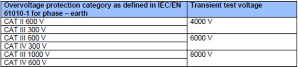
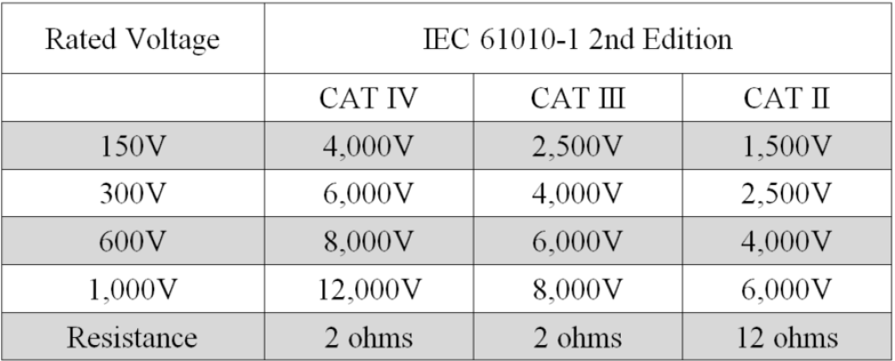
I have recently been reviewing the technical details for a popular brand of lever type splicing connector and, according to the information on the manufacturer’s website, the connectors are only rated for use in overvoltage category II applications. My understanding is that for a fixed wiring installation to comply with BS 7671, all equipment must be rated for overvoltage category III (regulation 443.6.2 and table 443.2) i.e. be capable of withstanding an impulse voltage of 4 kV. The certification data, also published on the manufacturer’s website, states that the connectors have only been tested to 2.5 kV.

I have queried this with the manufacturer, who advised that the 4 kV electrical strength test only applies to IT equipment.

I may well have misinterpreted the requirements, but I would be interested to hear anyone else’s views on this.

Parents
  • Slightly an aside but it is worth observing that the same category (I, II, III IV) for the same voltage (230V usually for us) requires different impulse test voltages, although the only thing that changes in going down to a safer a category is the fuse it has come though.

    ~Now this may seem a  bit odd, as clearly a fuse does not reduce the voltage of a transient - but it does limit the available current/time if something unexpected induces an arc event, and cuts the power off safely.

    So the higher test  voltage has the effect of  ensuring a larger gap between bits of metal, meaning in turn that even though more current is available, the striking of a self sustaining arc remains unlikely.

    This sort of thought is especially important when skating about with spindly meter probes where it is rare but not unknown to accidentally short adjacent terminals.  So removing the covers from the meter probes in effect lowers you a grade or two - i.e. a given length of  bare metal is more dangerous on the main bus bar than it is on the supply to a bell transformer.

    As I said earlier, the actual spacing between a few free flapping wago's is a bit of an unknown. It is however very possible, and so required, to test the flashover between the internals of a 3 pin socket or a lamp holder where the metal and what holds them apart is fixed.

    quoting definitions from https://www.gambica.org.uk/static/d96bb734-348d-478e-b0cba3b50fc35940/Guide-to-Overvoltage-Categories-and-Measurement-Categories.pdf

    Note that we are now onto a later revision than this refers, but the general push is unaltered.

    CAT I

    CAT I is applicable to instruments and equipment, which are not intended to be connected to the mains supply. Because the available energy is very limited, this category is normally not marked on the equipment.

    Examples: low voltage electronic circuits, load circuits of bench power supplies, etc.

    DefinitionCAT II

    CAT II defines circuits which are intended for direct connection into mains sockets or similar points. The energy in such installations should be limited to below 100 A continuously (or below 500 A for voltages not exceeding 150 V). The maximum available continuous power must be limited (for instance by a circuit breaker) to not more than 22 000 VA.

    Example: a device connected to a 240 V mains socket with 13 A fuse (energy limited to 3100 VA)

    DefinitionCAT III

    • CAT III is for circuits which can be connected to the mains installation of a building. Energy is limited by circuit breakers to less than 110 000 VA with the current not exceeding 11 000 A.

    Example: 110/240 V distribution boards, busbars, or equipment permanently connected to the 3-phase power supply (e.g. electric motors).

    DefinitionCAT IV

    • CAT IV includes circuits which are connected directly to the source of power for a given building. There are very high levels of available energy (e.g. limited only by the power transformer) and arc flash can occur.

    Example: measurements on a cable connecting the power transformer and a building (i.e. before the circuit breakers in the building).

    In addition to the label “CAT”, the maximum voltage must be marked. This voltage is the maximum voltage between live and ground of the circuit or the same overvoltage range.

    <
  • But these are only according to BS EN IEC 61010-1, and not true of all product standards (and IEC 60664-1 along with BS 7671)

  • True, but 60664-1 uses the same impulse test  limits for the same voltage case and these in turn re-appear in in tables F1 and F5 and set the required creepage and air gap clearances.

    So the choice of 3mm contact gaps in mains switches for showers etc comes immediately from the 4kV impulse test. If we really only had to hold off 230V RMS and not open against a high current, then a contact gap of about half a mm would probably do.

    It is not too surprising that the various documents advise similar things.

    M

Reply
  • True, but 60664-1 uses the same impulse test  limits for the same voltage case and these in turn re-appear in in tables F1 and F5 and set the required creepage and air gap clearances.

    So the choice of 3mm contact gaps in mains switches for showers etc comes immediately from the 4kV impulse test. If we really only had to hold off 230V RMS and not open against a high current, then a contact gap of about half a mm would probably do.

    It is not too surprising that the various documents advise similar things.

    M

Children
  •   Agreed test voltage levels are the same.

    However, the thing that's not the same is the descriptions of what the overvoltage Categories apply to vs BS 7671 and IEC 60664-1. They are "roughly the same" but the lines are very blurred I think.