Generator earthing....Again!

Hi All,

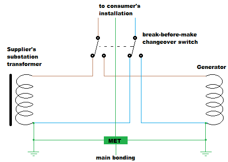
We've just installed a 400A manual changeover switch for a client that requires a backup generator (Not permanently installed - as It's being supplied by a generator hire company as and when there are power outages) It's a semi rural location and they seem to get power cuts several times a year.

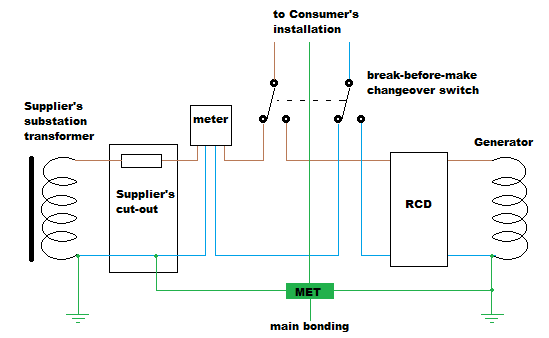
The generator company aren't being particularly forthcoming with information regarding the sets they will be supplying (Other than saying they all have in built earth fault Leakage protection) 

The existing supply is TNCS & I know we can't rely on the DNO earthing during a power cut. With this in mind and little more information to go on from the generator company,  Should we be installing a Rod(s) and just ensuring we have a resistance lower than 20 Ohms.  Is there anything else I need to consider, Obviously my concern is ensuring that any existing protective devices will still operate under fault conditions whilst supplied by the generator.

Given that  411.4.2 now recommends an electrode at the point of supply, I assume we have no real issue with a combined  TT / TNCS arrangement!

All thoughts are more than welcome,

Thanks,

Tim

Parents
  • Yes, you'll need your own local electrode. That won't make it TT though - in island mode you'd normally have a TN-S arrangement (check the generator has a N-PE link, introduce one if not) and in grid mode the electrode is just another bonded extraneous-conductive-part. Obviously the change-over switch should switch all live conductors including N, so that the generator's N-PE link isn't in-circuit when running off the grid.

    And yes, you'll have to check overcurrent protective devices given that the generator will likely have a much lower ability to supply fault currents than the grid (effectively a might higher Ze, although loop testers won't usually give you a sensible reading as the generator's AVR etc can fool the meter's mechanism). At worst (and if poor discrimination can be tolerated) a suitable RCD close to the generator might do.

       - Andy.

  • If it helps, a couple of diagrams we've used before:

    basic layout:

    Swicthed alternative generator, TN

    and more specifically for TN-C-S grid supply (you may or may not need the RCD):
    Generator, switched alternative, TN-C-S

       - Andy.

  • Obviously the change-over switch should switch all live conductors including N, so that the generator's N-PE link isn't in-circuit when running off the grid.

    Andy
    Could you direct me to the relevant legislation regarding the 'obviously' bit.
    I see many 2 pole single phase COS's, switched line and neutral but for 3 phase we seem to have what is described as 3 pole and neutral type, presumably a bolted neutral terminal and 4 pole type where we would be switching the neutral as a matter of course

  • Could you direct me to the relevant legislation regarding the 'obviously' bit.

    Generally BS 7671 reg 444.4.6 - the system shall be earthed at one point only (i.e. only on N-PE link can be in-circuit at a time).

    Legislation wise (in the UK), it's the Electricity Safety Quality and Continuity Regulations - regulation 8(4) - "A consumer shall not combine the neutral and protective functions in a single conductor in his consumer’s installation." as the arrangement effectively turns the linked N and PEs into PEN conductors.

    3-pole change-over switches would be fine when switching between alternative loads, but usually not between alternative sources.

       - Andy.

  • Many thanks. That's not quite the information I received via the NICEIC. It unfortunately seems to depend on who you speak to nowadays on the helpline.

  • seems to depend on who you speak to nowadays on the helpline.

    Rest assured, you can easily get multiple, often contradictory, opinions from here too!

       - Andy.

  • Many thanks. That's not quite the information I received via the NICEIC. It unfortunately seems to depend on who you speak to nowadays on the helpline.

    I can confirm ESQCR reference made to by Andy, also see Regulation 21 of ESQCR, which mandates BS 7671 when you have a generator that can provide a switched alternative supply to the grid, and also mandates that the switching arrangement does not permit the standby generator to operate in parallel with the grid (unless, as identified in G99, the generator is suitable for operation as a grid-connected generator too ... this is possible with some inverter output generating sets, where the inverter is type-tested for G98/G99 operation).

  • This is a standby generator for a village hall in the wake of Storm Arwen.It'll only be used when the DNO supply goes down.
    Ironically during said Storm Arwen when the rest of us in the area were without for 4 and 5 days that particular hall wasn't affected by power cuts at all!!

  • This is a standby generator for a village hall in the wake of Storm Arwen.It'll only be used when the DNO supply goes down.

    One of the reasons for the ESQCR requirement that the generator has to be switched, so it can't operate in parallel with the grid, is to help protect those working on distribution network cables from "back-feed".

Reply
  • This is a standby generator for a village hall in the wake of Storm Arwen.It'll only be used when the DNO supply goes down.

    One of the reasons for the ESQCR requirement that the generator has to be switched, so it can't operate in parallel with the grid, is to help protect those working on distribution network cables from "back-feed".

Children
No Data