DP RCD for Solar PV?

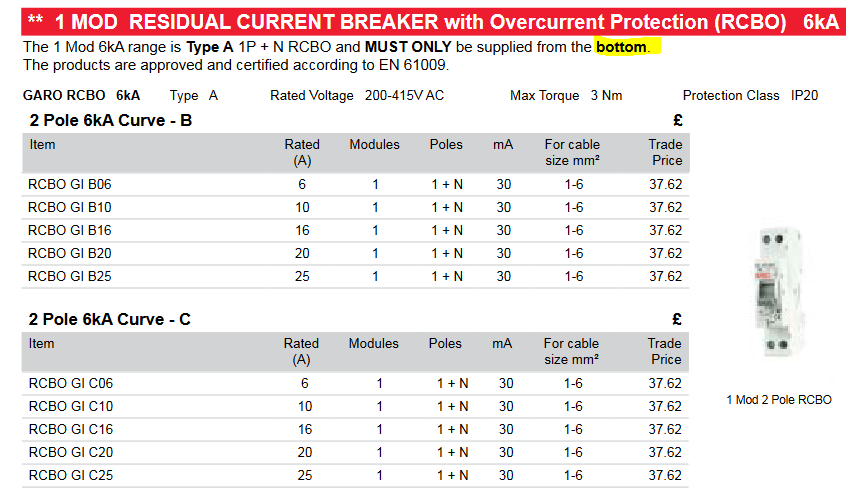
We are currently installing solar pv systems, and have had a third party at one of our installs carrying out an EICR. They have flagged a C2 for the RCBO we have used only being single pole.
In section 712 of BS7671 ‘Special Locations – Solar PV’ we cannot see a regulation that states that a double pole RCD is required. Any advice on this matter would be greatly appreciated.
Parents
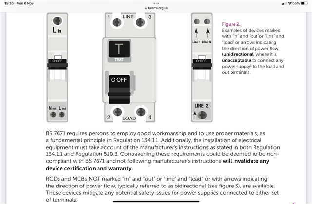
  • www.beama.org.uk/.../BEAMA-Technical-Bulletin-Connection-of-Unidirectional-and-Bidirectional-Protective-Devices.pdf

  • Thank-you that's interesting, very interesting. I wonder what the exact mechanism for causing damage to the device is. I'm having difficulty in imagining how arc chutes would be at all bothered if the voltage waveform happened to be out of sync.

       - Andy.

  • I may be able to offer some clarification - all "electronic RCD" designs have a fairly bosky operating solenoid, and a series triac or similar high power semiconductor that acts as a switch to apply the L-N voltage to it to fire it.

    However, to make a coil that pulls in strongly with anything from the worst case drooping supply during fault, to the full 230V+10% needs quite a bit of space - but  the saving grace is that it does not need to be continuously rated, as after 40msec or whatever, the power is removed when the contacts open. (similar economies of rating  apply to the test resistors in some designs, and if for any reason the contacts do not open the resistor does instead...) so a coil  is wound that is OK for 60V steady state or something, and on full mains it is grossly over driven but for an acceptably short time.

    If the electronics that operates the solenoid is on the load side, then of course this all works really well, and the trigger circuit can simply come on and stay on, until the power goes off. Except, of course,  that if the supply is on the wrong side it never does go off, and the driver electronics and the coil slowly cook even after the contacts have done their thing.....

    It is not too hard to design electronics that removes the trigger signal after a certain interval and that can be relied upon regardless of supply direction, but it is a deliberate design decision to do that, and not one that all designs incorporate.

    (The apparently easy way would be to wire the trigger coil in the same way as the test resistor actually so that it gets its live from one side of the contacts and its neutral from the other - but there are also problems with  that sort of design in that it is possible to wire it up in a way that the neutral of the 'dead' side is then still connected to the live via the coil and the trigger after  it is supposed to have tripped. )

    Mike.

  • Thanks Mike - that makes a lot of sense.

    I've had a look at the type of RCBO that's on my PV system - looking  at the front  there was no indication of in/out or line/load - terminals just marked 2/N and 1/N so according to the BEAMA document I should be OK. I then noticed a label on the side that seems to suggest that 1/N should be line and 2/N load though (so should I start worrying again?)

    RCBO label

    Looking closely the test circuit does look to go through a 3rd contact so I guess they're recognised the problem and sorted it.

    Anyone got any ideas on the "arc extinguishing / short-circuit characteristics impaired" problem that the BEAMA document mentions?

        - Andy.

  • Refer to the BEAMA guidance, it shows terminals marked Line and Load in your photo.

    www.beama.org.uk/.../BEAMA-Technical-Bulletin-Connection-of-Unidirectional-and-Bidirectional-Protective-Devices.pdf

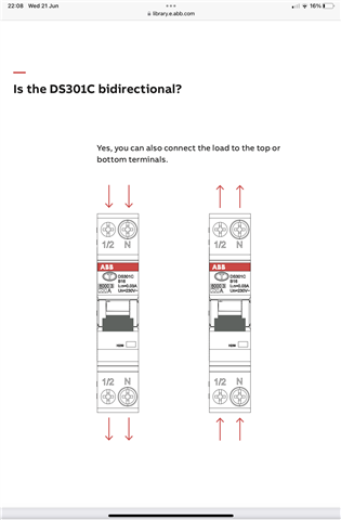
  • As opposed to:

  • I think you should start worrying again. Contact the makers - it may just be a labelism or it may actually matter.

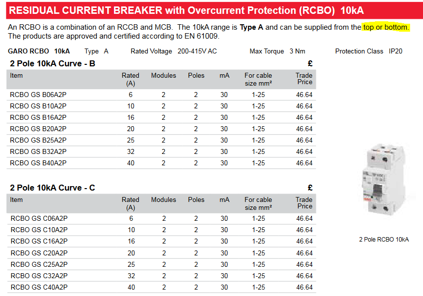
    is it the Garo one ?

    If so you are out of luck I am afraid.

    should have used  the two module width one


    Mike

Reply Children
  • I am getting a bit confused here. The BEAMA guidance refers to both MCBs and RCDs. I can see how an RCD in a split load CU could be run backwards (for want of a better description) but if the fault is before the RCD, it will not trip; and if it is after it, a fault in the consumer/meter/DNO tails seems pretty unlikely.

    Why would you connect a PV array to a final circuit which is protected by an RCBO? Is it not a distribution circuit, which accordingly, does not need RCD protection?

    What you might do is to put an RCBO downstream of the PV array, but the array would be connected to the supply terminals and the distribution circuit (to the CU) to the load side, so no problem there.

    Now think of night time. The supply side of the RCD is not energised. The load side is energised by the grid. So what are we worried about now? Is a fault on the wrong side of the RCD a realistic proposition?

    My apologies if I am missing something.

  • Well if the inverter makers instruction require it, it needs to be protected by an RCD (or double pole RCBO equivalent)...   But part of the problem  of inverters is that they do not generally provide enough over current relative to normal load current to operate conventional ADS in any sensible time, if at all. So for faults to earth, when running on an inverter derived supply, the RCD is needed to meet disconnection times. However, for systems that cannot run as an island, i.e, without grid power, it is not so important, as the grid always provides enough fuse-blowing current.

    However, one of the increasingly popular features of inverter PV, especially systems that include a storage battery, is the ability to operate as a generation island, and power essential functions in a power cut. In such a case, the RCD performs an ADS function, perhaps the only ADS function, depending on the strength of the inverter.

    Mike

  • Is it not a distribution circuit, which accordingly, does not need RCD protection?

    Would be needed for soft sheathed cabled concealed in walls (in my case I've used BS 8436 cable so I could get away without a 30mA RCD strictly speaking, but preferred to have it anyway).

       - Andy.

  • Mike, thank you - I see what you mean. If the grid has gone off, a dead short across a 4 kVA array will not bother a 16 A MCB (or 15 A fuse) but perhaps a battery would produce sufficient current?

  • Fair comment! So if there is any doubt about the functioning of an RCD, why not ensure that the distribution circuit is not soft sheathed and buried in plaster?

    From what I can see in my neighbourhood, the norm is to bring the PV output down externally in SWA or similar to somewhere near the DNO's service cable.

  • but perhaps a battery would produce sufficient current?

    Battery systems fault currents into the a.c. side are still limited by the electronics in the inverter - so still only a small factor above Ig.

    From what I can see in my neighbourhood, the norm is to bring the PV output down externally in SWA or similar to somewhere near the DNO's service cable.

    Ah, using SWA on the d.c. side is another point of contention - as there's no ADS from the panel output, it's meant to be protected by  double/reinforced insulation - which SWA doesn't usually provide. OK if the SWA is on the a.c. side of course. There again some inverter manufacturers seem to ask for RCD protection anyway.

       - Andy.

  • Quite. Actually I'd not hold my breath for that 4KW array to do a fat lot with a 13A fuse either unless it is very sunny or there is a DC battery to help it along a bit.
    Now for an L-N fault or overload, the inverter output collapses until the load is reduced to a level it can sustain - and no harm will come to the wiring, but everything will 'brown out' or 'black out' until the fault or extra load is removed.
    However if this extra current is due to the sort of fault to earth that might actually also shock or even electrocute someone, we would appreciate a rather more prompt disconnection. Enter the RCD stage left to save the day.

    M.