Cable Sizing for 2 nos x 400W Floodlight

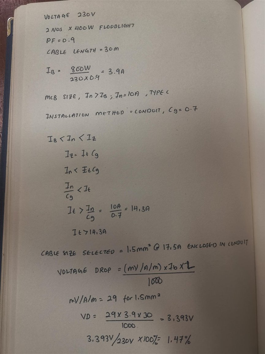
I'm trying to design one single line diagram (just for learning session) and one of my circuit is having 2 nos. x 400W Floodlight with 1.5sqmm Cu/PVC cable, with 30m cable length, MCB rating 10A all the calculation such as load current Ib, MCB rating In, derating factor, cable carrying capacity and voltage drop is shown in the above photo.

Based on my calculation, my Ib < In < Iz is  3.9A < 10A < 17.5A respectively, with voltage drop of 3.933V @ 1.147% from 230V, 

However, after discussing this with several knowledgeable individuals and referring to previous single-line diagrams that I've encountered, they've indicated that 1.5sqmm might not be sufficient, instead they requested me to change it to 2.5sqmm. (I do understand 2.5sqmm is better than 1.5sqmm in terms of cable-current carrying capacity, and voltage drop).

My query is, where might my calculation have gone wrong in this context?  


  • You are quite right - an 800 watt ideal  load at the end of 30m of 1.5mm2 or even 1mm2  cable will be absolutely fine from a voltage drop perspective - indeed you could drop the MCB to 5A as well.

    But..

    1) Certain types of flood light have surprisingly high inrush (ten times running perhaps) and struggle to 'strike' if the voltage droops too far during that phase.

    2) Mechanical strength - 2.5 mm is not too fat to work with easily, but is slighly  less likely to be damaged by pulling in, and has a copper size that fits the sort of terminals that folk  use in outdoor gear rather better.

    And no one wants to dig it up to do it twice when asked to add an one extra light or socket.

    Mike

  • Thank you for your asnwer:

    1) Certain types of flood light have surprisingly high inrush (ten times running perhaps) and struggle to 'strike' if the voltage droops too far during that phase.

    - for this design, I'm using C type breaker rather than B, to solve the inrush current. But I'm not sure whether this is a practical solution. Need to check it again.

    2) Mechanical strength - 2.5 mm is not too fat to work with easily, but is slighly  less likely to be damaged by pulling in, and has a copper size that fits the sort of terminals that folk  use in outdoor gear rather better.

    -in my humble opinion, the damaged done by cable pulling work is due to poor workmanship. Even if I use 1.5sqmm Cu/PVC cable for 2 nos x T8 LED tube, if the electrician / worker have wrong method / poor workmanship and etc. the cable will still get damaged. 

    And no one wants to dig it up to do it twice when asked to add an one extra light or socket.

    - this justification is acceptable, I do agree with you, in the event where there is a necessity to add one or more lighting, then my existing 1.5sqmm wont be sufficient anymore.  

    Thank you once again for sharing your input. 

  • the breaker firing  is not usually the biggest inrush problem - or at least if it is, then other things are also probably wrong. But during the inrush, the volt drop is potentially 10 times higher - this does not matter too much if the device can still strike at the reduced voltage of 210V or whatever, and  I suspect a lot of this advice is generally for traditional pulse starter discharge lights and maybe less of a problem with electronic drivers and LEDs.

    Mike.

  • Perhaps it is related to power loss. Using a larger cable will have a higher initial cost, but in the long run, you will recover it by reducing the energy loss over the years. You can use Ohm’s law, hours of usage, and copper resistance values to calculate the kWh lost per year and the cost per year. You can then calculate the payback period by dividing the initial cost by the annual savings. Appendix 17 of Bs 7671 is expected to become a new part in the near future.

  • Other thought was to to fault protection - what's the PFC at the supply end like? Above about 3kA a C10 might have an energy let-though higher than the withstand of a 1.5mm² Cu conductor.

       - Andy.

  • not an absolute requirement since you have In ≤ Iz you can go down the deemed to comply route of 435.1 but some might prefer the added reassurance.

       - Andy.

  • With the changes to the C&G EVSE courses there is a sudden resurgence in interest in doing full circuit design calculations as electricians are failing the domestic and commercial course exam, because they can’t do the full circuit design calculation.

    I did it all properly twenty years ago when I did the old C&G 2400 Design, Erection and Verification course, but have rarely done a full calculation since, so I am out of practice and having to think about it.

    Looking at your calculation it seems you have not multiplied the wattage of the lamps by 1.8 as recommended for discharge lighting in the IET guides, such as the IET On-Site Guide on page 136.

    You have simply said they are 400 watt floodlights, not exactly what they are, multiplying the wattage by 1.8 may need to be considered, we would almost have certainly been doing it twenty years ago.

  • not multiplied the wattage of the lamps by 1.8

    I thought that was to account for an unknown, possibly quote poor,  PF (plus control gear) - the OP seems to have used PF=0.9 (presumably accurate for those particular fittings).

       - Andy.

  • You dont mention voltage drop limitations but at around 1.5%, unless the circuit is commencing at a DB where the Ud is already stretched, it is well within deemed to satisfy constraints.

    I do not think your calculation is wrong. I think that you have set out your calculation neatly, although if you are doing a written exam, I would advise you to indicate the table from which you are extracting your data. For example, Installation method B from Table 4A2, Cg selected from row 1 of Table 4C1, It from column 4 of Table 4D1A, mv/A/m from column 3 of 4D1B etc. That way, if a value is wrongly selected, at least the examiner can quickly see your mistake and award some marks, even if the calculation is wrong.

    For those "knowledgeable individuals" who would determine you to be wrong, ask them for their computations.

    Below, row 1 employs overload and assumes fault protection by virtue of 435.1, row 2 employs only fault protection as overload may not be needed, row 3 uses the X1.8 that Sparkingchip referred to.

    Below that is how Ud is calculated in Ireland.

    Unless there is some kind of I2t issue, Ud or Zs limitation, you can see that you could even use 1.0mm2

  • It seems like I get your point (or maybe not...) please let me know if my understanding now is align with your explanation.

    In normal operation, both my breaker and cable capacity won't have any problem.

    during the starting (inrush current), the C-type breaker which will trip between 5-10 times rated current also will not operate , however the cable (in this case 1.5sqmm, current carrying capacity of 17.5A) won't be able to carry the inrush current and resulting in cable melting/damage etc.

    so the voltage drop that I calculated is only meant for normal operation, in practical I have to consider the inrush current as well. is this what you are trying to explain?

    Thank you.