SWA plus separate cpc

While on a site last week, I noted 25mm2 4-core swa cables being installed on a ladder and for some reason, each one had a 10mm2 separate copper cpc cable tied to the swa. The furthest run is about 50m from a DB where the EFLI is 0.1 ohms.

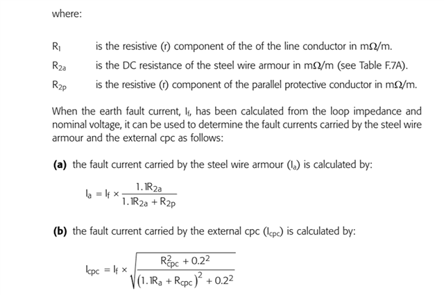
Just as an academic exercise, I set about trying to establish the current division between the wire armour and the separate 10mm2 copper cpc using the formulae in the IET Design Guide. Factoring in the usual temperature increases, 70 for phase in the swa, 60 for the wire armour and 30 for the separate cpc, the expected impedance was 0.25 ohms with a fault current (using 230) of 1140A dividing to 672A in the wire armour and 826A in the separate cpc.

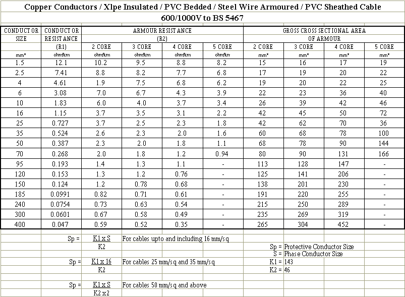
Data used; R1 at 20C = 0.73mohms, R2a at 20C = 2.1mohms and R2p at 20C  = 1.83mohms. Likely there is no real merit in the pedantic adjustment for temperature, but hey!

If someone felt sufficiently bored and had an old fag packet, would they be kind enough to check my results? Strangely, if one reduces the separate cpc to 2.5mm2 the fault current is 936A dividing to 244A in the wire armour and 727A in the 2.5mm2 separate cpc. That is counter intuitive but perhaps expresses a limitation on the formulae or, much more likely, a limitation on my understanding!

Parents
  • well that formula is just the the real parts, so DC resistances , up to the 0.4 X - ignoring the  'X' here.
    the bit that is not the live core resistance R1 is just 1,1 * resistance of armour (R1a), in parallel with the copper (R2b)
    We might have expected not to have the 1.1 factor with the wire armour, but perhaps that is assumed to be warm and the copper cold?
    One might expect that once one resistance is a lot lower than the other it takes the lions share of the current- just like any other pair of wires in //. no magic in the formulae, other than I do not know why they bother to make a special formula out of it.  as it is sort of obvious.

    Not sure how you got

    Strangely, if one reduces the separate cpc to 2.5mm2 the fault current is 936A dividing to 244A in the wire armour and 727A in the 2.5mm2 separate cpc. 

    I don't!.

    Here  is my mental (non book approved method) logic

    the copper resistance of 50m of 1mm2 will be ~ 16*50 = 0.8 ohms cold, and more like 1.0 ohms hot.   (the happy estimator rule of 16.. not the exact book figure)

    So 10mm2 will be 0.08 ohms cold more like 0.1 ohms hot, and

    2.5mm will be 320 milli-ohms cold, 400 milli-ohms hot.

    Now for the armour, 25mm four core (BATT cables data see below.) 2.3 ohms per km, so 50m of it is 1/20 of that so,  0.115 ohms.

    So when in // with the 10mm2 expect current share to be 115/215 of it down the copper and 100/215 if it down the iron.almost equal split.

    (here the round loop resistance is the building external 0.1 ohm, plus outbound  the 25mm copper core (35 milliohms) plus coming back as these two as a parallel pair ~ 50 ,milliohms )

    it is PSSC 230V/0.185 ohms = 1.3kA...


    When in // the 2.5mm (I assume you remove the 10mm for this test - do you ?) then 115/(115+320)  = 115/435 down the thin  copper and 320/435 - i.e. most of it. down the steel armour.

    (here the round loop resistance is the building external 0.1 ohm, plus the 25mm copper core (35 milliohms again) plus these two as a parallel pair ~ now 80 ,milliohms )

    it is PSSC 230V/0.205 ohms = 1.1kA...


    Note that the 'it' PSSC  changes in only slightly  each case as the fixed external 0.1 ohms is more or less half the loop total .

    Mike

  • Mike,

    I am not so sure that is as obvious as you say. The current division is, apparently, difficult to predict and will not divide on the basis of simple DC resistance. The top formula is a vector arrangement. Formula (a) seems strange to me which possibly reflects that vector consideration. For simple resistive split the current through resistor A is evaluated by Ia = total current * RB/RA+RB which is the opposite of what formula (a) is indicating. 

    The current split will then be a vector sum. I stuck it through excel and it is not too far away from what that guy Pythagoras was on about.

    Maybe you would humour me when you get a mo and run the numbers through the formula they give? :)

  • Apologies for the lack of clarity - my comment about parallel resistances  Rp= Ra*Rb/(Ra+Rb ) was not bothering to look at the two lower equations but only at the upper one - and that is the parallel formula with a few hangers on like the 'assume a constant inductance' term at the end.

    While l we can crash through the lower two formulae with that book method, and I am happy to try that,  it will be tomorrow now as I will need to be awake to avoid random sign errors, inversions and so on and the talking cobblers associated with late in the evening and a beer.

     before we do, can I  note that I already  consider the two lower formulae for Ia and Icpc have to be more than  a little bit suspect just on a casual inspection. (which is why I ignored them earlier)

    The Ia one, at least in the limit of  very small and very large values of Ra clearly predicts  a totally non physical behaviour.

    First, as the R2a tends towards  0 ohms, we get an Ia that also tends to zero, when it should tend towards  carrying most of the total fault current.

    Secondly  for a very large value of R2a - many  times Rcpc. it implies the armour current tends then towards 100% of the total fault current  - when I hope we'd expect the fraction it carries to fall with increasing resistance....

    The intent of the last equation is unclear to me.

    I am not clear as to what is meant by Icpc, (as opposed to I2a) - it is clearly not the total fault current, nor is it dependent on any reactance, so I do not see what mister pythag is doing there though I agree the sqrts make it looks like he is.

    If Icpc is the current in the parallel copper then it is also suffering a similar problem with asymptotic values.

    Mike

Reply
  • Apologies for the lack of clarity - my comment about parallel resistances  Rp= Ra*Rb/(Ra+Rb ) was not bothering to look at the two lower equations but only at the upper one - and that is the parallel formula with a few hangers on like the 'assume a constant inductance' term at the end.

    While l we can crash through the lower two formulae with that book method, and I am happy to try that,  it will be tomorrow now as I will need to be awake to avoid random sign errors, inversions and so on and the talking cobblers associated with late in the evening and a beer.

     before we do, can I  note that I already  consider the two lower formulae for Ia and Icpc have to be more than  a little bit suspect just on a casual inspection. (which is why I ignored them earlier)

    The Ia one, at least in the limit of  very small and very large values of Ra clearly predicts  a totally non physical behaviour.

    First, as the R2a tends towards  0 ohms, we get an Ia that also tends to zero, when it should tend towards  carrying most of the total fault current.

    Secondly  for a very large value of R2a - many  times Rcpc. it implies the armour current tends then towards 100% of the total fault current  - when I hope we'd expect the fraction it carries to fall with increasing resistance....

    The intent of the last equation is unclear to me.

    I am not clear as to what is meant by Icpc, (as opposed to I2a) - it is clearly not the total fault current, nor is it dependent on any reactance, so I do not see what mister pythag is doing there though I agree the sqrts make it looks like he is.

    If Icpc is the current in the parallel copper then it is also suffering a similar problem with asymptotic values.

    Mike

Children
No Data