SWA plus separate cpc

While on a site last week, I noted 25mm2 4-core swa cables being installed on a ladder and for some reason, each one had a 10mm2 separate copper cpc cable tied to the swa. The furthest run is about 50m from a DB where the EFLI is 0.1 ohms.

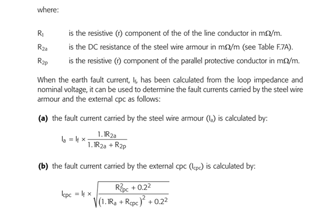
Just as an academic exercise, I set about trying to establish the current division between the wire armour and the separate 10mm2 copper cpc using the formulae in the IET Design Guide. Factoring in the usual temperature increases, 70 for phase in the swa, 60 for the wire armour and 30 for the separate cpc, the expected impedance was 0.25 ohms with a fault current (using 230) of 1140A dividing to 672A in the wire armour and 826A in the separate cpc.

Data used; R1 at 20C = 0.73mohms, R2a at 20C = 2.1mohms and R2p at 20C  = 1.83mohms. Likely there is no real merit in the pedantic adjustment for temperature, but hey!

If someone felt sufficiently bored and had an old fag packet, would they be kind enough to check my results? Strangely, if one reduces the separate cpc to 2.5mm2 the fault current is 936A dividing to 244A in the wire armour and 727A in the 2.5mm2 separate cpc. That is counter intuitive but perhaps expresses a limitation on the formulae or, much more likely, a limitation on my understanding!

Parents
  • The formulas you have extracted from the Electrical Installation Design Guide 5th Edition - where developed by the ERA in a report commissioned by the ECA. This  was issued to them in May 2007. The ERA conducted various test on sample cable setups to support the report.

    ERA Report Number: 2007-0334

    This report is 'Commercial-in-Confidence' and the ECA have Copyright.

    So I will not be quoting it in any detail.

    The ECA published a book - Guide to the Wiring Regulations (17th Edition) written by Darrell Locke.
    I attended some meetings with him, on another matter, and he gave me a copy. At that time the book was awaiting a number of appendices, this report being one of them. The appendix concerned is No 16, which I now have - this contains the ERA report.

    So you may be able to track it down.

    The point of my post is that the formulas you have extracted do not align with those in the report - probably a typo!

    Equation (a)
    Ia = RHS  should have the RHS from equation (b)

    and equation (b) should have the RHS from equation (a).

    My money is on the original report!

    Regards

    Geoff Blackwell

  • ha!  Many thanks Geoff.

    Now I know where it has come from I can see it. Indeed a very clear case of the typo fairy strikes !


    That also actually explains the empirical origin of the rather odd  constant inductive 'x' assumption, and also provides evidence what I have thought/ suspected  for a while, that the wires of the armour of an SWA are quite far from a solid cylinder of magnetic material surrounding the cores, and behaves much more like an air gapped core of negligible additional inductance and so  not so different to to non-magnetic  copper or aluminium armour.

    Looking at the annex shows that the return current likes to stay as close as possible to its associated  outbound line core, minimising magnetic 'loop' area and does indeed not share quite as per the ratio of the measured DC resistance, giving a noticeable preference to moer current going down the armour.

    This may come a surprise to some, but thinking as one with an RF transmission background, what appears to be happening here is that the (long and thin) loop formed by the inner core and the external CPC has a larger area than that (equally long, but flatter) loop formed between the inner live core and the armour around it, so there is less energy expended (= voltage drop) in setting up the magnetic field in the space between the flow and return currents.

    It also means that as  these formula are based on the results of tests on 95mm and 185mm2 cables, the effect is likely to be less serious with smaller sizes with more resistance and less inductance due to smaller wire and insulation diameters and therefore also closer current paths and smaller magnetic loops. It  also means that these formulae are likely to  be less accurate when the external CPC is not closely tied beside the SWA - indeed if the external CPC parts company with the SWA for any distance, that will be like adding a lumped inductance in series with the path of the the external CPC.

    For thinner SWA and external CPCs, it will all collapse back towards  the more easily understood resistive division case.

    I'm happier - though the abridged advice, as well as needing the typos correcting could probably do with some 'range of usefulness' comments.

    Mike.

  • First of all, thank you to GB!

    I do not have access to the text referred to. Could you give me an example of the current division calculated/plotted for any combination? 

  • Yes well at 73+ my ability to respond adequately to such a request diminishes daily!

    The ERA report is complex. It specifically addresses two cable sizes 185 mm2 and 95 mm2 . They carried out a number of tests on sections of the cable using fault currents around 1000A. The report contains a great deal of detail (30 pages) and really must be read in it’s entirety. I only have a paper copy.

    The book I mentioned above can be found on Amazon: https://www.amazon.co.uk/Guide-Wiring-Regulations-2008-7671/dp/0470516852.

    The only problem with that is I do not know if it contains appendix 16 – that was a separate download and I can no longer locate it. If you have contact with the ECA they may help.

    From the report I can say that it:

    1) addresses whether additional cpcs are necessary;

    2) develops a model that includes inductive reactance;

    3) suggests that the results from model developed do not differ greatly from a simple analysis using a purely resistive model and the division of current rule.

    I would say that the model you use is a matter of engineering judgement.

    Simple model

    Ia = If * Rcpc/(Rcpc + Ra)

    Icpc = If * Ra/(Rcpc + Ra)

    However you really need to read it for yourself.

    Finally, you must always bear in mind that short circuits are dramatic events that can produce results that are difficult to accurately predict. This is especially true during the first five cycles of a large short circuit as asymmetrical fault currents may occur and these ruin calculations that assume sinusoidal conditions.

    I have designed some systems using the ERA model and I have also checked them against manufacturers information such as one second cable withstand data. There are a number of reasons why you may wish to run an additional parallel cpc on a distribution circuit. The report does caution that you should not use small cable sizes as these may be damaged – it mentions that it might be unwise to used a cpc less that ¼ the size of the main conductors.

    I hope this is of some assistance.

    Regards

    Geoff Blackwell

Reply
  • Yes well at 73+ my ability to respond adequately to such a request diminishes daily!

    The ERA report is complex. It specifically addresses two cable sizes 185 mm2 and 95 mm2 . They carried out a number of tests on sections of the cable using fault currents around 1000A. The report contains a great deal of detail (30 pages) and really must be read in it’s entirety. I only have a paper copy.

    The book I mentioned above can be found on Amazon: https://www.amazon.co.uk/Guide-Wiring-Regulations-2008-7671/dp/0470516852.

    The only problem with that is I do not know if it contains appendix 16 – that was a separate download and I can no longer locate it. If you have contact with the ECA they may help.

    From the report I can say that it:

    1) addresses whether additional cpcs are necessary;

    2) develops a model that includes inductive reactance;

    3) suggests that the results from model developed do not differ greatly from a simple analysis using a purely resistive model and the division of current rule.

    I would say that the model you use is a matter of engineering judgement.

    Simple model

    Ia = If * Rcpc/(Rcpc + Ra)

    Icpc = If * Ra/(Rcpc + Ra)

    However you really need to read it for yourself.

    Finally, you must always bear in mind that short circuits are dramatic events that can produce results that are difficult to accurately predict. This is especially true during the first five cycles of a large short circuit as asymmetrical fault currents may occur and these ruin calculations that assume sinusoidal conditions.

    I have designed some systems using the ERA model and I have also checked them against manufacturers information such as one second cable withstand data. There are a number of reasons why you may wish to run an additional parallel cpc on a distribution circuit. The report does caution that you should not use small cable sizes as these may be damaged – it mentions that it might be unwise to used a cpc less that ¼ the size of the main conductors.

    I hope this is of some assistance.

    Regards

    Geoff Blackwell

Children
No Data