SWA plus separate cpc

While on a site last week, I noted 25mm2 4-core swa cables being installed on a ladder and for some reason, each one had a 10mm2 separate copper cpc cable tied to the swa. The furthest run is about 50m from a DB where the EFLI is 0.1 ohms.

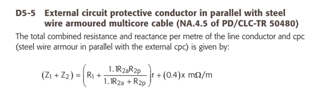
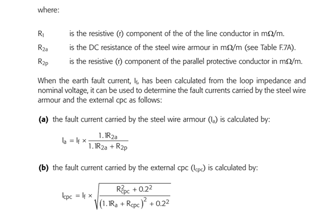
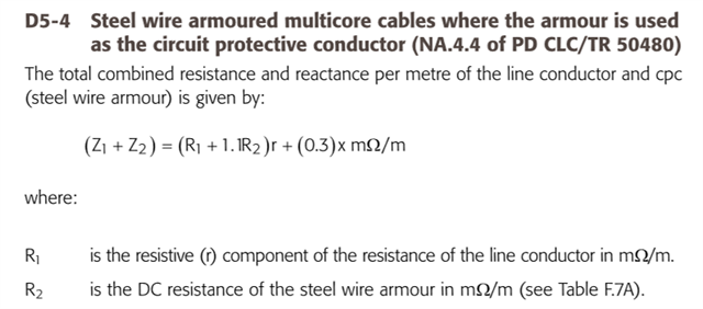
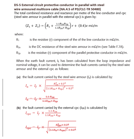
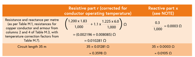
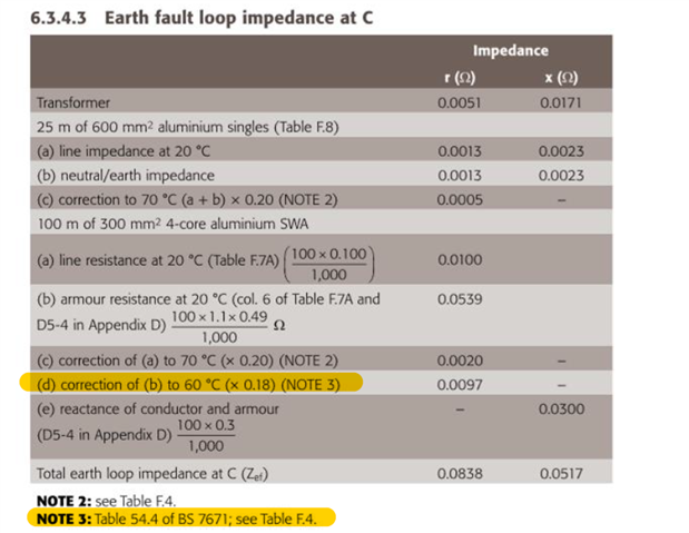
Just as an academic exercise, I set about trying to establish the current division between the wire armour and the separate 10mm2 copper cpc using the formulae in the IET Design Guide. Factoring in the usual temperature increases, 70 for phase in the swa, 60 for the wire armour and 30 for the separate cpc, the expected impedance was 0.25 ohms with a fault current (using 230) of 1140A dividing to 672A in the wire armour and 826A in the separate cpc.

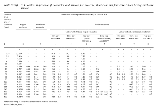
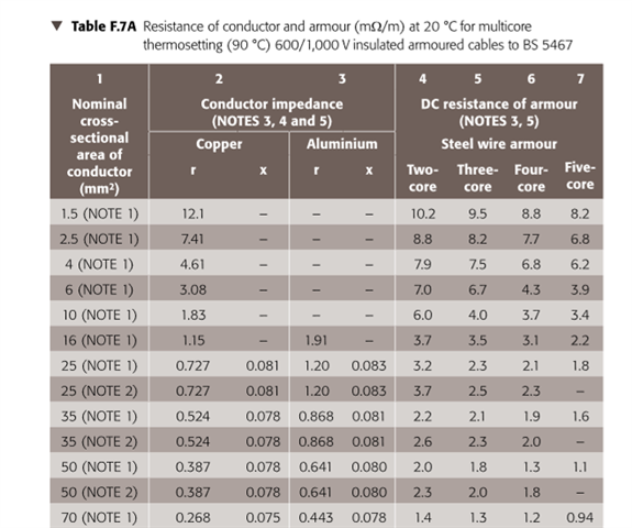
Data used; R1 at 20C = 0.73mohms, R2a at 20C = 2.1mohms and R2p at 20C  = 1.83mohms. Likely there is no real merit in the pedantic adjustment for temperature, but hey!

If someone felt sufficiently bored and had an old fag packet, would they be kind enough to check my results? Strangely, if one reduces the separate cpc to 2.5mm2 the fault current is 936A dividing to 244A in the wire armour and 727A in the 2.5mm2 separate cpc. That is counter intuitive but perhaps expresses a limitation on the formulae or, much more likely, a limitation on my understanding!

Parents
  • A handy guide, but it does not seem to be displaying the tables correctly with the sizes that are a problem in red.

    Using SWA as a CPC the guide for your reference. (gadsolutions.biz)

  • JP may recognise some of the words on that web page as the same as something he too has circulated on the topic but as you say with the vital formatting to identify the problem sizes slightly stuffed..!!

    John does not consider anything more than an ohmic split- which will be OK for smaller SWAs The formulae above are really for when inductance is starting to bite over simple resistance - hence its derivation using test results from 95 and 185mm cables - hence my comment on it really needing some extra notes on the range of applicability.

    Mike

  • And so it goes on, strapping a supplementary cps to the swa cable, completely dismissive of cost to the client or environmental impact. I asked my 2391 class yesterday, all contractors and all would feel uncomfortable about relying on the wire armour alone. Several confirmed that every consultant-designed job they had ever been on specified the separate cpc. It is now part and parcel of standard practice, like pulling a cpc into a steel conduit wiring system.

    However, my concern is more from the academic side. I note that City and Guilds are quite rightly encouraging reference to the IET Design Guide for the 2396 Design Erection and Verification course so as Mike says, some extra notes on the range of applicability would be good rather than a bald set of formulae that come without explanation or example. In fact, had an example been given the errors pointed out by GB would likely have been spotted before publication.

    A sample calculation exercise for one of the revised City and Guilds  EV courses comes with their suggested answers. Although it is only swa cable without an external cpc, it uses the following formula from the IET Design Guide;

    Now, anyone who has ever sat a City and Guilds exam of this type will know how pedantic the examiner can be on adjusting for operating temperature! The sample answer given raises the R1 and R2 values as normal but ignores the additional reactive component, perhaps because the cable is only 6mm2.

    Any way, what I want to establish is (a) is the formula a vector addition or is it just a bit of rough maths ignoring the fact that you ought not to add apples and oranges in the same way we add Rs to Zs in simple loop impedance calculations and (b) the application of a1.1 uplift to the DC resistance of the SWA is to account for the magnetic effect of the conductors within the containment, which the wire armour is not, so if the 1.1 uplift accounts for a change in reactance, perhaps to the phase but applied to the armour, then why further adjust for operating temperature as reactance will not be affected by it. 

    As a foot note for GB; Being 73 is not an excuse. I remember you well for your sterling contribution to the academic and technical side of our industry over very many years. Please do not duck under the quilt just because of increasing years. Every time I see your name pop up on this forum, I am straight there! You probably do not appreciate your value to light-weights like me!

    Oh, and by the way, my neighbour is an electrical contractor and farmer, he is up at 6am every morning to tend to his cattle and off down the road to some other farm to fix milking machines and the like. He has just turned 84!! 

  • However, my concern is more from the academic side. I note that City and Guilds are quite rightly encouraging reference to the IET Design Guide for the 2396 Design Erection and Verification course so as Mike says, some extra notes on the range of applicability would be good rather than a bald set of formulae that come without explanation or example. In fact, had an example been given the errors pointed out by GB would likely have been spotted before publication.

    I think whether an example would have identified the issue depends when the errors were introduced in the process ... basically, equation type expressions are not easy in publishing packages, and there's no ready "export from Word" or similar. As you will have noticed, there are some other issues with the subscripts of one of the formulas here too.

    I can confirm that the two formulas in D5-5 (a) and (b) are "swapped", and the formulas (as per PD IEC/TR 50480) should have been provided as follows:

    The formulas in the paper Geoff Blackwell refers to eventually founds its way into the UK national annex to PD IEC/TR 50480, which is referenced in the EIDG.

    I'm sure the suggestion about an example for the "parallel cpc" will be considered seriously for the next Edition ... but I have some thoughts of my own below that might prompt some discussion.

    Now, anyone who has ever sat a City and Guilds exam of this type will know how pedantic the examiner can be on adjusting for operating temperature!

    Agreed. Annex M (section M2) of the 5th Edition of the IET Code of Practice for EV Charging Equipment Installations does include an example for armour (alone) used as cpc, and different temperature correction factors are used for the copper and steel ... although the assumption here is that the armour will be at the cable conductor operating temperature before the fault begins, which it is unlikely to be. It also includes the note that reactance is not  adjusted for operating temperature.

    And so it goes on, strapping a supplementary cps to the swa cable, completely dismissive of cost to the client or environmental impact.

    I have some concerns (apart from getting the maths right) about the validity of the practice of supplementary cpc in all cases:

    • We all know that BS 7671 is supposed to cover only single-fault conditions. The debate here, is whether the "single-fault" is a severed cable or not ... because if it is possible to sever the cable and not the external cpc, the external cpc can't be taken into account for that fault. A severed cable (or at least damage to more than one conductor) must be considered as a "single fault"  because we use the three-phase bolted fault current to determine maximum prospective fault current.
    • In addition to the above, for direct-buried cables (where unintentional damage of an unseen cable is more likely, and may damage or sever the SWA and not the parallel cpc) Regulation 522.8.10 says the armour has to be suitable for use as a cpc.

    But I'm not 100 % decided and I think the designer needs to take the actual risks into account before deciding whether to go ahead with the practice.


    Finally, I've heard some say that we can't rely on the SWA as a cpc because of issues with poor termination in glands ... for me, that's a step too far. DO IT PROPERLY (it's not like we don't have all the fancy tools available at very reasonable prices compared to 25 years ago)!

  • Graham, I see that you recognise the adjustment of the SWA probably ought not to be at 70C. Fair enough but the correction should be to 60C and should be 1.18 rather than 1.225. Likely not matter one jot in the real world but whoever did the sum would be marked down in the 2396! I do remember the time when the calculation for 70C copper was to 115C (the average of 70 and 160). 

    In any event, the 1.1 uplift is a strange consideration. Is it saying that the resistance of the wire armour is increased by the magnetic effect of itself? 

Reply
  • Graham, I see that you recognise the adjustment of the SWA probably ought not to be at 70C. Fair enough but the correction should be to 60C and should be 1.18 rather than 1.225. Likely not matter one jot in the real world but whoever did the sum would be marked down in the 2396! I do remember the time when the calculation for 70C copper was to 115C (the average of 70 and 160). 

    In any event, the 1.1 uplift is a strange consideration. Is it saying that the resistance of the wire armour is increased by the magnetic effect of itself? 

Children
  • In any event, the 1.1 uplift is a strange consideration. Is it saying that the resistance of the wire armour is increased by the magnetic effect of itself? 

    That's one way of looking at it, but I think it's possibly a simplification of a more complex situation, and what we have is an approximation at experimental results?

    the correction should be to 60C and should be 1.18 rather than 1.225

    Interesting ... we're using an internal conductor temperature of flexible cables for fixed installation wiring now? The armour is inside the cable, so unless you know the thermal properties of both the filler and the sheath, we just don't know ... BUT by the same token, perhaps we ought to consider the uninsulated cpc of T&E in the same way?  ... we really don't know its temperature(even if it was a full load), so the ONLY option is to assume it's the same as the current-carrying conductors ?

    Made worse by not knowing the installation conditions, and distribution of temperature around a concentric cable ... unless the lay-up is helical with a parallel-axial wavelength suitably short with the length of run, again it's another unknown !

    Pedantry is one thing, but sadly ...

  • Graham, setting aside Fowlers statement on pedantry, I believe this is where the 60C is justified;

  • Graham, setting aside Fowlers statement on pedantry, I believe this is where the 60C is justified;

    A little care, perhaps, is needed here ... these are tables for K for the stated values of initial and final temperature (see top of page 200, in 543.1.3, 'The values are based on the initial and final temperatures indicated in each table.'

    That does not mean that every cable has those initial temperatures ... it may be a "good enough" assumption (the tables say they are "assumed" initial and final temperatures) for the adiabatic criterion, but that doesn't mean one shouldn't err on the side of caution when trying to establish whether an impedance is low enough to operate a protective device effectively?

    What would the examiner expect if the cable was bunched, or installed in an underground conduit with other cables?

    In the particular case we are talking about - parallel copper cpc - these are often bunched with the cable, the assumed temperatures in Table 54.2 may not be valid.

    In the case of the example of CPEVCEI 5th Edition, the temperature correction factors used in the example for the armour are actually stated (in another table) so the reader doesn't have to work it out for themselves.

  • Graham, yes, I hadnt thought of it that way and had just slavishly followed Chief Examiner comments (and some of the older texts like BD Jenkins who shows calcs to 60 for the wire armour, albeit as an average of initial and final temps). It all becomes  unnecessarily arcane when one considers the current practice of using 218.5v that used to be 240v then 230v to calculate Zs not to mention the uncertainty of the value of Ze. I believe GB and Mike are probably spot on with that micrometer and axe analogy. 

    I just spotted a howler in my own Excel calcs regarding some swa values. I have been extracting data from this table from Paul Cooks wonderful commentary on the 17th. 

    I couldnt understand why my calculations using old fashioned approach of separate r and x value was just so far apart from the one in the CPEVCEI 5th Edition until I twigged the r value for the 70C swa was significantly different to the value for 90C thermosetting given in IETEIDG. One is 3.9 and the latter 6. There must be significantly less csa of wire armour in the 90C cable?

  • Be wary of modern cables claiming to be BS6346 (the PVC clad SWA) as that standard was withdrawn over ten years ago, and the XPLE standard ' 5467 is the more common.

    Worth a read of this wiring matters article Of course there is plenty of old cable about the place. But the diameter and no of the steel wires is not guaranteed the same and can be a source of confusion.

    Except for BATT cables data, where their values are not always quite the same as those tables either. but the variation of armour resistance between their XPLE and PVC offerings is shown side by side, so is easier  to see.

    Mike

  • I am typing this for insertion below GKs post of two days ago. I dont know why the reply rarely gets posted like that and ends up at the foot of the thread. Nor indeed, does the quote button work Windows 11 PC. It does on my Ipad.

    the correction should be to 60C and should be 1.18 rather than 1.225

    I am convinced that there is a dusty room somewhere in the dungeons of City and Guilds HQ where equally dusty, bespectacled, old men pour over IET publications in search of secreted minutiae to ambush the unsuspecting candidate. Below from current EIDG.

  • Yes, I think that, assumption is absolutely fine in some cases, hence that hasn't been updated ... but not others, and in particular perhaps shared ducts for EV charging which is the other example quoted.

    I agree with your suggestion that some more examples ... perhaps with the various assumptions used noted, as here ... would be of great benefit to everyone concerned.

    At the last update, we were trying our best to move the publication on to align with PD IEC/TR 50480 because of a number of issues relating to calculations, and following the update/withdrawal of some of the armoured cable standards, and the data they provided.

  • I have a copy of a previous EIDG book and I calculated the total loop impedance at C (Zef) using the formula

    where 

    r=0.0815 ohms

    and 

    x=0.0597 ohms

    Zef=0.1 ohms

    Ief=2500 Amps

    How does this compare to the latest edition of the book? Is there a significant difference?

  • Based on the previous calculations that do not apply PD IEC/TR 504801, the final result is marginally higher, which is more conservative. I will adhere to this method because the empirical measurements correspond to the calculations performed using the prior method. So why change This method I have applied repeatedly when the actual measurements have matched  the calculations.? 

  • Your lack of response implies that you concede to my argument. Furthermore, as I have demonstrated in my calculations, the addition I use is optimal and does not require any alteration. What is the rationale behind proposing a new standard, other than generating revenue from book sales? It seems that the bureaucrats are meddling with the matter without justification.