SWA Cable Gland Adapter Piece

Hello 

Can anyone offer some help regarding the use of  fabricated SWA cable gland adapter/extension pieces?

During installation works, our contractor has made off 2No 5C, 240mm2, SWA cables too short to reach the gland plate.

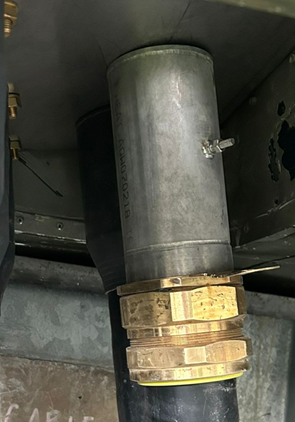
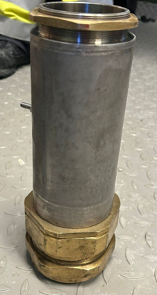
To avoid replacing the cables, they have site fabricated two "Extension pieces" from some 316 S/S to allow the cables to be terminated (shown below).

We have some reservations accepting the installation, therefore I am seeking some clarity on the following points:

  • Is this an acceptable installation method under BS7671?
  • What specific clauses in BS7671 would these pieces have to conform to (511.1?)
  • is there anything in the Regulations that would allow this installation to be rejected?

Thank you.

Parents
  • I don't recall a BS for "oops extension pieces" (to mis-quote Starrett's oops-arbors) - in which case 511.2 is probably the way to go.

    In the first photo it looks to have been installed at a bit of a jaunty angle though  ... which might make me suspect that the extra lengths involved are acting as a lever and putting more strain on things than would ordinarily be the case ... which if can't be corrected would make me wonder about 134.1.1 (Good workmanship .. and proper materials).

       - Andy.

  • Normally on smaller cables one uses a short length of the same size conduit as the gland hole to do this, much as one would for pyrotenax cables. Modern way seems to be to waste a length of metal trunking and use a few inches  of it or have an adaptable box with nothing in but the cores and a bit of wiggle length.

    However, as this stuff is presumably about 3 inches in diameter and the glands will look like soil pipe fittings, so perhaps not at this scale.

    So, first how well does it make electrical contact - would it handle the full PSSC?

    Then, does it satisfy the environmental requirements of the location ? - looks not to be IP anything but I don't think the bare gland was IP44 either...

    Third, Is it putting an excess strain on the gland plate or box ? - if so the cable fixings may need revisiting.

    So probably could be OK, if done well, but of that we need to be confident.

    Oh, also, why is there  a machine screw sticking out the side ?

    Mike.

  • The oops arbors look good for folk like me who sometimes  cut twice and measure once.... or something like that. Thanks for pointing them out, I was not aware and originally thought you were joking.. No use to the original post of course, but now I know what I need for Christmas. Sad isn't it.

    Mike.

  • My guess is that the set screw is there as a kind of earthing stud to bond to.

Reply Children
  • earthing stud to bond to.

    And if so, on a circuit with 240mm2 conductors it looks woefully under-size for carrying the sort of PSSC one might imagine.

    What is it - M4 perhaps ?  M12 or perhaps M14 would be more like it.
    Unless it is something odd, like a 10km run for a voltage drop compliant supply to a single 13A socket of course. But I think we can assume not, and at 0.2 ohms per km, guess at something in the region of a 400- 600A supply with a few % volt drop, and then a PSSC of 20kA or more is quite credible and should be allowed for - hence my concern about the current handling by things that just hang on by the threads where it meets the box and the gland. (the armour is probably made of 90 or so  2mm dia or 60 or so 2,5mm dia steel wires, and the cable will have a 1 second withstand of at least 30kA. To preserve the rating that sort of steel cross section needs to be in the extension too.)

    M.