Alternative solar supply available at point of use Domestic kitchen

Hello newbie : 

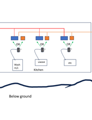
Imagine Domestic kitchen Usual array of sockets and under counter appliances

Wish Introduce  Alt solar supply sockets alongside existing grid supply sockets , Thus : User can select alternative ( solar ) supply as opportune arises  at point of use ( battery storage/ inverter system)

Eg plug microwave to alternative socket  as power opportunity ( battery charge is available ) 

(Alt supply sockets are entirely dedicated from inverter as typical OFF grid system ) 

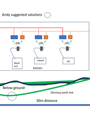
Question  Is there  anything in regs preventing this ; Thought: The sockets must be somehow labelled / identified as alt supply  Any ideas to meet regs? 

Remark : similar to external generator supply but with NO changeover switches . Outlets are dedicated 

thanks Ms Otis 

Parents
  • there are some diagrams here https://electrical.theiet.org/wiring-matters/years/2021/84-march-2021/island-mode-earthing-arrangements-new-guidance-in-the-second-edition-of-the-iet-code-of-practice-on-electrical-energy-storage-systems/

    that clarify the proper switching, Graham is one of the authors...

    Mike

  • thanks again Andy and all I was getting excited there it was do able > BUT  These examples seem to be all about  changeover switches Isolating

    circuits from grid / reconnecting to inverter : 

    If your still with me Please check again the concept : Perhaps I am breaking new territory If you would please indulge me one more time : to be sure 

    GO and stand in your kitchen : Look at the socket outlets  Now imagine next  to EACH is installed another : These added sockets to be fed directly and independently  connected via solar/ battery  inverter (separate distribution board)  All separate: wiring : everything: 

    These "alternate"  sockets go live whenever  ( you)  consumer turns on the inverter . The grid sockets are also live same time. Now imagine you consumer go and choose alt supply source by simply unplugging any appliance eg microwave and plugging into adjacent "alt" socket: Thats the point of it 

    No changeover switches to existing loads  Inverter system was thought as fully  independent : 

     OH  damn !!!!  by your good observations  we see a problem with earthing to appliances  IF  we introduce a separate  TT earth. One chassis at different potential to others.  

    Last ditch  is could we avoid  sperate TT earth and simply link the  inverter earth system to incoming grid earth. ?  ( I think you are saying that would mean BOTH Ground and Neutral  were linked.  Inverter to grid incoming.  

    Question remains IS this possible and so avoid changeover switches converting alt source to island   Grateful thanks  again to all still on this thread

    Ms O 

  • Question remains IS this possible and so avoid changeover switches converting alt source to island   Grateful thanks  again to all still on this thread

    Only if the inverter is arranged to prevent back-feed of any description to the grid - which is possible in non-separated inverters, or inverters that contain transformers.

    Note that semiconductor devices are not (currently) considered to be isolators.


    There are still provisions regarding earthing of both systems to conform to IEC 60364 and BS 7671 in the UK.

  • I think I'm with you - you just happen to have two distinct LV systems inside the same building. I'm not seeing any fundamental problems with that (I think Graham is considering the possibility, all too common with some of the latest inverters, that they can do all kinds of clever things like taking over from the grid supply during a power cut, or that the battery could be charged from the grid supply). So we're not talking either about a switched alternative nor a parallel source.

    You will need suitable equipment of course - especially your chosen inverter will need to be capable of running as a TN-S system with a N-PE link (as you'll be feeding >1 appliance) (many smaller/cheaper inverters, indeed petrol generators, are configured as unearthed "separated" system and aren't suitable for feeding multiple appliances via a fixed installation and may or may not be convertible) Your "off grid" system will need a reliable means of earthing - i.e. a local electrode. That does NOT make it a TT system though (for that you'd need two electrodes, one for the "source" and another separate one for the loads) and as it shares an environment with the grid supplied system, the two earthing systems will need to be connected together. You electrode will look like an exposed-conductive-part to the grid Earth (like a bonded water or gas pipe) and likewise the grid Earth will appear to be no more than an another exposed-conductive-part to your off-grid system. (That does bring in some requirements - e.g. the conductors from the grid's earth to your electrode are treated as main bonds for the grid system - so the minimum conductor size is a fairly chunky 10mm² even for a typical domestic - potentially larger. Physically that's almost certainly unnecessary as the resistance around your electrode will limit the current to something quite small, but the regs don't recognise that).

    I'll try to draw a diagram when I get a chance - a picture can be  lot clearer that words...

           - Andy.

  • I really do think that you are making things very difficult for yourself. OK, I stand in the kitchen and look at a double (white) socket with toaster and kettle. You want a red socket (they must be distinguished somehow) next to it. The sun is shining and now what? Do I have to unplug both appliances and switch them over (even though it is mid-day and I am not going to toast bread) or can I leave one in each?

    Why do you want to "break new territory" when there is a well trodden path?

  • Why do you want to "break new territory" when there is a well trodden path?

    Cost, potentially.

    Also possibly the fact that some products on the market currently have some in-built functionality that doesn't easily, or  fully, align with Chapter 82 of BS 7671 ?

  • Andy:  Dear All  Frustration from some I can see Forgive : " Why reinvent the wheel ? " >>   How and why this solution See end of this post.  BUT remain very grateful for all comment adverse or despairing hope they keep coming 

    If nothing else and this thread becomes a general discussion of earthing / earth rods ./  car charging earth rods / 100 various earth rods now nearly touching  in the street? : I would much appreciate such an educational opportunity  Where actually does the current flow This proposal perhaps a ready  focus .  Gosh : in living memory when boys were told to go out and pee on the old GPO earth rod so the phone would work .

    Andy thankyou so much for this reply   Yes  A diagram would simplify the outlook. for comment : Look forward to that.I attach my own visual so we can all visualise the approach so far  . Can send in ppt if useful. I know there are many kinds of inverter  I have not bought anything yet.  Still need to cost it..

    Why this approach : Wanted to go solar and some verision  off grid/ battery  looked more appealing if not cost effective and simple.

    Accidentally saw a USA video Generator back up: Changeover style This kit seemed to have individual switches for  each existing circuit to switch it from  grid to generator.  Looked great   Ah now in UK doesnt exist:  we have large power changeover switches. So switching a range of chosen circuits :Grid or Generator   All or Nothing : Like it or not

    So here I have pondered a solution so its not all or nothing > It is User selection  AT POINT OF USE> Off grid is always a matter of opportunity and weather forecast. ?   So here we can choose target appliance to match power available .  Winter or summer Coould choose a smaller battery / inverter if I select what to run . And its so simple 

    In my home kitchen is by far the largest electricity user  Suspect most. So it make sense to concentrate the opportunity there . And time is right My old kitchen ripe for revamp.     Do hope we can find a way. Let you know how it all goes if we do  Ms O 

    PDF

  • OK, here's my attempt at a diagram (it's not intended as a full design or even a recommendation, just what I think you're suggesting - so as to keep the discussion on track).

Reply Children
  • Andy  ! OH  Bingo ?  Attach my updated visual in line with andys suggestion .  Andy have you ever done this ? Is this a common dual supply solution ?  All comments welcome please : 

    Two  points

    guess it is expensive to test an earth rod  Would this be required as part of final sign off ? 

    Does solar panel mount  system also require earth . ? 

    Was figuring on laying both dc and ac cables underground as 10mm for all. 30 + meter distance  Trying to be sure /only want to trench once 

    thanks again.   Ms O 

    PS " Point of USE select  system :  Figure only  have to size Kwhr system for max load( not add up total)  Probably washing/mc  + a bit 

    Ms O PDF

  •  Andy have you ever done this ?

    Not exactly - I've had some involvement with UPS systems (for IT server rooms) though, so some of the principles are familiar.

    guess it is expensive to test an earth rod  Would this be required as part of final sign off ? 

    If you've got a grid supply, with a bit of care, a rod can be tested using an ordinary loop tester (something every domestic electrician should have). There is a bit of debate about a suitable value - the traditional (BS 7430) advise was a (somewhat arbitrary) 20Ω - which can sometimes be difficult to achieve, but some more modern text books are more flexible and you might get away with something closer to 200Ω for simple setups like this. I think the electrical energy storage systems code of practice covers this.

    Does solar panel mount  system also require earth . ? 

    That's probably a "it depends" answer.  A few years ago the answer was "almost certainly not " - as the d.c. was either extra-low-voltage (<50V)  (so no earthing required for shock protection) or if higher voltage was protected by double/reinforced insulation (so again no earthing required) - I gather than the thinking has moved on a bit now (with all sorts of other considerations coming into play, from lightning to EMI to modern transformerless grid-tied inverters that don't necessarily provide separation from a.c. side) so sometimes the answer might now be different. I think it's covered in the PV code of practice, but I don't have the latest version to hand.

    Was figuring on laying both dc and ac cables underground as 10mm for all. 30 + meter distance  Trying to be sure /only want to trench once

    There's a simple method to make sure you dig once - install a duct (I like "twinwall").  A size or two larger than you think you need. You can then draw in additional or replacement cables at a later date.

    d.c. underground (as I hinted earlier) might be a bit of a issue. Not because it's d.c. but because it's usually part of an unearthed system. Normally underground cables need an earthed armour or similar -  the idea being that if they're hit by digging tools and damaged though to a conductor (which is surprisingly easy to do - as I once demonstrated with a steel wire armoured cable and a simple garden fork) - it'll short to earth and trigger off normal 'automatic disconnection of supply' to make it safe. If the system is unearthed that doesn't happen ... which might be a problem. (We have similar problems with d.c. PV cables concealed in walls - and the usual fix of using a 30mA RCD doesn't work either).  In theory an insulating duct with mechanical protection can be used instead of earthed armour, but the same level of safety needs to be achieved - which is difficult to demonstrate given it might have to resist anything from a garden fork to a mole plough to a JCB. There are possibilities, depending on the details (like the actual voltages and methods of shock protection in use) but the details will need working out. Some will require separation from "mains voltage" a.c. cables (So maybe two ducts, at least 6" apart?).

    The "all a.c." grid-tied approach (PV just has a local inverter, battery system has its own charger & inverter locally to itself) does make life a lot easier in these sorts of situations.

    PS " Point of USE select  system :  Figure only  have to size Kwhr system for max load( not add up total)  Probably washing/mc  + a bit 

    Don't forget the earlier points about starting currents - the grid supply is naturally very tolerant of little surges in demand (since everything is backed up by the almost limitless national grid) so such considerations are very often overlooked - little inverters without a mains backup have no such margin - and many will sulk or shutdown completely with relatively small overloads, however temporary.

       - Andy.

  • Was figuring on laying both dc and ac cables underground as 10mm for all. 30 + meter distance 

    Sorry, another thought has occurred to me - which d.c. cables are these? If they're between the charger and the battery, or between the battery and the inverter, then there will likely be significant voltage drop along their lengths (especially if the batteries are ELV, as the currents would then be higher). As well as the loss of efficiency, unless the charger/inverter had separate battery voltage sensing wires, the voltage drop will likely fool them about the battery state - the charger seeing a higher voltage than it really is - fooling it into thinking that battery is fully charged when it isn't; and likewise the inverter seeing a lower battery voltage - fooling it into thinking the battery has a lower charge than it really has (and so shutting down early). Just a matter of cable length, rather than being underground.

      - Andy.