Dealing with >30 mA Residual Current due to an industrial servo drive in a 'man cave' scenario on residential electrics? UK Based Location.

Hi All,

Long story short, I have a man cave that runs off my home's main board. The main board was recently upgraded and is 18th reg compliant. My workshop is fed with a 32A RCBO which then goes into a sub DB which has a Wylex Isolator and then feeds into another 32A RCBO.

I can run most of my machines without issue and I create 3 phase using VFDs. One specific Servo Drive however needs 3 phase and is fed from a VFD which then in turn powers the Servo Drive (so VFD into VFD). This trips my RCBO.

The manual suggests that the Servo Drive (7.5KW/ 10 HP) should sit behind a 200mA RCD, otherwise its likely to trip. This is their exact wording.

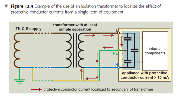
"Cause: the leakage protection switch trips after the servo spindle start-up. Reasons and countermeasures: 1.A plain leakage protection switch with a leakage protection value of 200mAis recommended; otherwise candle the leakage protection switch; 2.Use the specified leakage protection switch dedicated to servo(or transducer) with a leakage protection value of 30mA; 3.Add an isolating transformer between the plain leakage protection switch and servo driver."

What are my options in the UK to deal with this?

Thanks in advance.

Parents
  • What are my options in the UK to deal with this?

    Appropriate selection and erection:

    • Completely avoid socket-outlets rated up to and including 32 A (single-phase or three-phase).
    • Wiring system chosen appropriately (e.g. SWA).

    If TT, might not be easy ...

    Why is this so hard in domestic? Well ... it's not domestic equipment.

    And an issue you may well have in a domestic environment is electrical interference - this kind of VFD is most likely an industrial product.

  • Apologies, yes TT based home supply.

    Agreed, its more industrial hardware than 'home' stuff. I'm actually selling the lathe and the new buyer also wants to run it off single phase (probably part of the selling point of this specific lathe). He has much higher availability of single phase (Im limited to 32A), under correction he has >70 or 100 Amps. I cant ship a 2 ton machine that then doesn't work in his environment either, so trying to see if the Servo Drive's noise can be mitigated / dealt with somewhere.

    As far as I understand (and I'm not UK certified, despite being a qualified electrician - I work in IT now) is that above 32A there is some tolerance / leeway in the requirement for 30mA RCD sensing? So options are a)deal with the noise or b)increase the RCD tolerance level.

    Thanks

  • It is not 'noise' that trips the RCD. It is the filters that place capacitance between phase and earth to mitigate the noise (fast edged current pulses as the VSD commutes to slice the supply in turn can cause sharp spikes on the supply voltage - bad for other kit and for radio reception). The capacitors act as local reservoirs and mean that the  short sharp shock of current is limited to a small loop involving the VSD and the capacitors, rather than the shocks proagtaing along whole line back to the substation. Think of the caps rather like the tank on the loo - it allows a huge peak flow when needed in a small region, without needing an impossibly low impedance (fat pipe) back to the origin.

    The other way to do it, common in industrial or agricultural TT settings abroad  is to redesign  the EMC filtering to put the largest capacitance between Phase and Neutral, and then between N and E, but not directly  between  L and E....

    Without knowledge of the VSD and its internal or external filtering circuits, it is hard to recommend. What data do you have ?


    As Graham notes if you hard wire it in the right sort of cable you can sidestep a lot of this. A TT installation with an earth electrode good enough to fire  300mA ELCB is not especially difficult. If you are running more than tens of mA into the wiring earth through the filters, they are probably not the right sort of filters for that applicaion anyway.

    Note that in some designs, and quite a lot of literature, there is an unhealthy obsession in some designs with 'ground' or 'earth' as if it is magically at zero volts and never wobbles. At 50Hz this approximation may be OK but as far as fast events are concerned it is better seen as just another line that is terminated somewhere so far away relative to the events being filtered that it's exact termintation  is irrelevant.

    Mike

    (when I say long or far  comared with, that is to say that the electronics cannot know it is earthed - the buy the time the pulse gets down the earth wire, sees the termination and gets back to where it came, the stimulus is all over, time has moved on. In the world of sub-microsecond spikes, 'far' is a lot nearer than it is at 50Hz.)

    Mike.

  • a)deal with the noise or b)increase the RCD tolerance level.

    Well, both ... will be required (the "earth leakage" affecting the RCD won't go away on its own, nor will the "noise")

    There is another way of dealing with the RCD ("earth leakage") issue, which is explained in both the machinery electrical safety standard (BS EN 60204-1) and the VSD guides to use - use an isolating transformer at the machine itself - make a new "neutral to earth" connection on the secondary to run the machine from, connected to the cpc of the primary, so you limit the "leakage" to within the machine.

  • There is another way of dealing with the RCD ("earth leakage") issue, which is explained in both the machinery electrical safety standard (BS EN 60204-1) and the VSD guides to use - use an isolating transformer at the machine itself - make a new "neutral to earth" connection on the secondary to run the machine from, connected to the cpc of the primary, so you limit the "leakage" to within the machine.

    This is a diagram showing how this works, from IET Guidance Note 5 Protection Against Electric Shock, 2022 (see also Section 12.4.5 on page 104).

    Using a centre-tapped secondary (so PE connects to centre-tap and primary PE, rather than Neutral) can also help to deal with "noise" as well as the issue of "leakage currents" ... but protective devices and isolators on the secondary would have to be 2-pole as you'd effectively have two line conductors rather than a line and neutral (like the single-phase reduced low voltage system).

  • Thanks. I have put this servo drive behind an isolation transformer. I did also experiment with different N to E scenarios. At one stage I had floating voltage of 110V which I was able to get down to around 2V. I'm still seeing a bit of current between the chassis and Earth (circa 0.0.1A) however this is the machine before the servo is powered. I dont have hardware good enough to measure the 'spike'.

  • Many thanks for the detailed reply. I dont have tech details. I am waiting for Chinese New Year to end to get some further insight. They have been good in the past with other queries however in this case, not sure if its something they can help with.

Reply
  • Many thanks for the detailed reply. I dont have tech details. I am waiting for Chinese New Year to end to get some further insight. They have been good in the past with other queries however in this case, not sure if its something they can help with.

Children
No Data