
Are there any ElectricalOM users on here who can explain setting up the source details?
Thank you.
Not understanding this at all. For a 69KvA tx with a 6% impedance, I make the short circuit KVA to be 1150 and the KA circa 1.7.
How is the source Iscc the same as the line neutral in a three-phase set up?
It looks like the programme is not user friendly for a simple design where source details and cable details between source and installation are unknown.
How is the source Iscc the same as the line neutral in a three-phase set up?
I see that now. Since the three phase short circuit is Uoxcmax / Zp, the values will be the same at the source terminals. Presumably, when one inserts the characteristics of the cable from source to installation origin, the values given at the installation origin will reflect the intervening conductor impedances.
I assume you could therefore start with any appropriate standard tx and then input a connecting cable that will attenuate fault levels to a desired value.
I'm not sure that it does. I'm working from test results from the service head...or at least as close as possible to there. When putting all the parameters in the Isc is still 10.17... when I think it should be 20.34. (I may be wrong, that's why I'm posting on here). However, the downstream DB calls for the same short circuit currents when dealing with 3 phase MCCBs and single phase MCCBs. Hence why I'm posting for advice. I can't see how you would input information relating to the installation origin. NB. Lyle I've back calculated an input kVA of 69 to give a 100A per phase supply, and (I think from memory 0.98 Z% ) to give 10.17 kA single phase short circuit current.
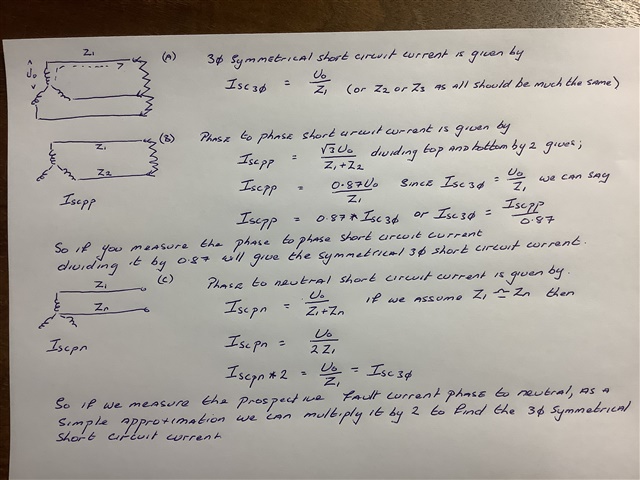
I hope you don’t think this patronising. It is an attempt to explain why we can make approximations of the three-phase symmetrical fault current by measuring the fault current between two phases and dividing by 0.87 or, as many do, by measuring the fault current between phase and neutral and multiplying by 2.
The key thing is accepting the premise that the three-phase symmetrical fault current is given by dividing the phase voltage by the impedance of one phase only.
Note that the phase voltage is 230v for a 400/230v system. Likely if design calculations were being made the voltage would be lifted by 10% to 253v.
No doubt in a real fault situation, strange things will happen to thwart neat text book explanations.
Surely it is not a 69kva TX - as far as I know, no such beast exists - this is a virtual transformer at the point of arrival of the supply to force fit the PSCC measured - in reality more likely to be a 1/8 or 1/4 megawatt lump and perhaps a hundred metres of street main cable . Actually if that is the software calculation method, then that is misleading, as there is a lot of difference in being close to a small transformer, where the impedance is largely inductive, and far from a big one (I see shades of the father Ted small / far away cow sketch here ) where the impedance is more resistive.
In a real fault this alters the degree of overshoot of the waveforms compared to a clean slice of sine-wave quite considerably and so ratio of the peak fault current to the RMS is higher nearer the TX.
But Lyle's method is fine in any case, though as I like easy rules of thumb, I'm a 'just double it' sort of person at least when sizing things, more forgiving reviewing designs of others that are already in place.
The lazier argument for double it goes like this. IF you have a 3 wire bolted fault, then at the point of fault, the voltage is zero - identical to that at the transformer star point, assuming all 3 fault currents equal there is no neutral current to speak of. . So the current is set by the line conductor resistances only. In the P_N loop test it was set by the series resistance of line and neutral conductors, likely equal. So for the 3 wire bolted fault, the current is double the LN loop test result. . Tada - no hard sums. Just wrong if the supply cable is reduced neutral of course. Of if you are close to the transformer and the supply is not just 3 identical resistors made out of the line cores of the supply cable.
Users of approximations, know your limits, as you might say. With a nod to one of Harry Enfield's historic characters..
Mike.

Hi Richard,
Apologies, but i'm still not sure what it is you haven't been able to achieve with the software. I would input the values in the boxes indicated by Spencer Henry . The only item that i have not input is the 69kVA source capacity, because you have not stated this to be the case. You can use any value in the source capacity box to check agains the supply limit - e.g. an agreed maximum demand value. If you do not click the "calculate short circuit" button then the fault current values will not update from your manually entered values and the calculations will be undertaken based on your values.
When i do this at my end the values propogate through the calculation.
We're about to take you to the IET registration website. Don't worry though, you'll be sent straight back to the community after completing the registration.
Continue to the IET registration site
