Minimum size of CPC

When using the Adiabatic equation, only to calculate the minimum size CPC, I am thinking that using the fault currents given in Appendix 3 of BS7671 rather than that calculated (UO/ZS) would give a more realistic outcome.

For example: A D6 circuit breaker is protecting a circuit where the calculated fault current is 328A. The table associated with Fig 3A6 in Appendix 3 of BS7671 shows that an overcurrent of 120A will operate the 6A breaker in 0.4s. Using these values and a K value of 115 results in a minimum CPC of 0.66mm2 (1.0mm2), whereas if you use the 328A the calculation results in a minimum CPC of 1.80mm2 (2.5mm2).

I cannot see a problem with using the lower value, but would appreciate confirmation and guidance from others.

  • I cannot see a problem with using the lower value, but would appreciate confirmation and guidance from others.

    There absolutely is a key issue with using the lower value, because that does not represent the actual prospective fault current at either end of the cable.

    However, potentially, also the 328 A value if that is calculated at the furthest point in the circuit is also a problem, because a fault may well occur at the "near end" of the cable.

    This is why designers ought to use an "adiabatic plot" over the characteristics of the protective device ... discussed in detail in Section 8 of the IET Electrical Installation Design Guide (EIDG).

    BUT

    There is another issue with the fact you're using circuit-breakers... as discussed in section 8.5 of the EIDG, if it's in the "instantaneous" portion of the curve, as 328 A or more would be, you need to use either:

    (a) The manufacturer's stated value of let-through energy I2t; or

    (b) The let-through energy I2t from the circuit-breaker product standard.

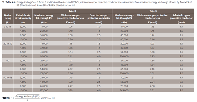
    You plug this let-through energy value in place of the product I2t, in the adiabatic formulas in 543.1.3 and 434.5.2, rather than calculating I and looking up t. THe let-through energy does depend on the actual fault current, so you need to know the range of prospective fault currents (near end and far end of the cable) and look up the let-through energy for both, and the largest calculated S is the one to use.

    The reason for this, is that, for a cpc, as well as 541.1,3, you also need to meet Regulation 434.5.2 (which relates to the selection of the protective device in relation to fault currents ... fault currents includes prospective fault currents for all of L-L, L-N and L-PE faults.

    If you want to use values from the product standards BS EN 60898 and BS EN 61009, these lead to the following minimum csa (copper conductors) for Type B and C circuit-breakers (see Table 8.6 of the EIDG) ... the use of manufacturer's data often leads to lower csa requirement:

  • The 0.4 seconds figure is too long - a real breaker will not be that slow once you are above 20times the rated current - hence the 120A - the highest possible level at which the internals of the MCB changes from being slow and thermal to being magnetic and fast.
    In practice you will struggle to damage a 1mm cable with a D6 breaker at any fault current that the breaker can break

    Mike

  • In practice you will struggle to damage a 1mm cable with a D6 breaker at any fault current that the breaker can break

    The data in the EIDG (Tables 8.7 and 8.8) doesn't support that assertion for all manufacturers' breaker (using manufacturer provided data)- even with Type C at 3 kA and 6 kA.

    But there's probably some "engineering overhead" in "cable fault survival" assumptions.

  • If as 541.1 allows, I select the size of the CPC rather than use the calculation method, I would be able to select a 1mm2 conductor based on the fact that the corresponding line conductor is also 1mm2.

    This then correlates with the calculation method outcome when the 120A generic value for a D6 circuit breaker (taken from Appendix 3) is used.

    My assumption, maybe naively, has been that the calculation method would nearly always produce a smaller CPC than the selection method?

  • I would be able to select a 1mm2 conductor based on the fact that the corresponding line conductor is also 1mm2.

    How? The combination of overcurrent protective device and line and neutral conductors also need to meet Regulation 434.5.2?

    So, if 434.5.2 is leading to 1.5 sq mm, this applies to L and N too. 434.5.2 applies in addition to


    Usually, though, with prospective fault currents under 1.5 kA, the energy let-through I2t taken from manufacturer data (for 6 A Type B and C circuit-breakers at least) would permit selection of 1.0 sq mm. It's probably true for many D6 breakers too.

    What is the manufacturer and part number/range of the D6 circuit-breaker you are using? I will see if I can get hold of the data to illustrate what  I'm saying.

    My assumption, maybe naively, has been that the calculation method would nearly always produce a smaller CPC than the selection method?

    Yes, it can but not always.

    It's worth noting that whilst our usual selection case of IZ ≥ In ≥ Ib (Reg 433.1.1) relates to protection against overload current, wheras Reg Group 434.5 relates to protection against fault current. Selection of a conductor size S has to satisfy both conditions (overload and fault) and therefore the highest S calculated using each of the Regulations (and of course, not forgetting volt-drop) is the minimum size to be selected.

  • The circuit breaker is a Hager NDN106A (6A 10kA SP Type D).

  • It's worth noting that whilst our usual selection case of IZ ≥ In ≥ Ib (Reg 433.1.1) relates to protection against overload current, wheras Reg Group 434.5 relates to protection against fault current. Selection of a conductor size S has to satisfy both conditions (overload and fault) and therefore the highest S calculated using each of the Regulations (and of course, not forgetting volt-drop) is the minimum size to be selected.

    Is the suggestion then, that for normal MCBs, the 2nd paragraph of 435.1 doesn't apply? (i.e. where a suitable overload protective device has suitable breaking capacity, it may be assumed that requirements for fault protection are met).

      - Andy.

  • Thank you,

    Just as an example, from the 2007 data sheet data sheet I quickly found on the internet for this device, I believe the let-through energy for the D6 would be as follows:

    • For Ipf = 3 kA, I2t = 5,900 A2s
    • For Ipf = 6 kA, I2t = 10,500 A2s
    • For Ipf = 10 kA, I2t = 15,000 A2s

    Rearranging the formula k2S2 ≥ I2t from Regulation 434.5.2, we have S ≥ {√(I2t)}/k ... which spookily looks just like the formula in 543.1.3

    k = 115 for copper conductors, so using the values above,

    • For Ipf = 3 kA, S ≥ {√(5900)}/115}, or S ≥ 0.67 sq mm, so minimum S = 0.75 sq mm (flex from connection unit etc) or 1.0 sq mm (fixed wiring)
    • For Ipf = 6 kA, I2t = 10,500 A2s, or S ≥ 0.89 sq mm, so minimum S = 1.0 sq mm
    • For Ipf = 10 kA, I2t = 15,000 A2s, or S ≥ 1.1 sq mm, so minimum S = 1.25 sq mm (flex from connection unit etc) or 1.5 sq mm (fixed wiring)

    So, if you know the prospective fault current at the DB end of the circuit is 6 kA or less, then 1.0 sq mm is OK for the D6 NDN106A, but if it's closer to 10 kA, you will need 1.5 sq mm. We already know it's lower than 3 kA at the remote end ...

    This applies to cpc and live conductors equally.

    For another manufacturer's product, or if Hager have provided a more up-to-date data sheet, the let-through energy values will be different, leading to potentially different results.

  • Is the suggestion then, that for normal MCBs, the 2nd paragraph of 435.1 doesn't apply? (i.e. where a suitable overload protective device has suitable breaking capacity, it may be assumed that requirements for fault protection are met).

    The first paragraph of 435.1 says that the requirements of Sections 433 and 434 apply to the device.

    The the third paragraph says the second paragraph is an assumption and you might need to check for circuit-breakers, and the calculation I just posted proves that there are limitations (even with this current-limiting circuit-breaker).  The assumption is, however, generally good, and it would be unusual to have > 6 kA on a B6 in a final dis-board, but it could happen.

  • It doesn't seem like a particularly useful assumption, if it needs to be checked even for common MCBs. (using generic BS EN 60898 data there are whole swathes where energy let-though data would suggest larger conductors than Iz ≥ In would give (even ignoring the dubious maths of 1 ≥ 1.06 etc). If it's really only a safe assumption for fuses, would it be better just to say so?

       - Andy.