DC Isolators

Hi All,

I am a little confused around Current ratings on DC Isolators.

Last week I watched a you tube video from on the supposed differences between AC & DC Isolators.

The demo was with Scame 590 series

A 20A AC isolator and an identical one marked 16A for DC. Identical contacts, materials etc.

The DC uint was only said to be 16A rated with 2 contacts in series.

I have never really thought of contacts in series as a means of increasing current capacity, more parallel contacts/cables etc for this application.

The suggestion in the video was not that current was increased but the series contacts provided more air gaps in the circuit, thus it was better able to quench the Arc.

I am tempted to do a little test see the effects on the first and subsequent contact at FLC.

I have worked in and with DC for most of my career in one way or another but never really considered Arc damage.   

Can anyone point me toward some calculations for determining the DC rating of contacts from a given AC Rating for a similar utilisation code AC22/DC22 for example?

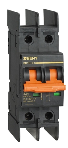
Here is an example of an Isolator claiming 63A rating but at the same time 32A on a per contact basis. 


Thanks

Martyn.

  • I can't answer your question, but when I worked on designing motor controllers for large DC motors (up to 650A) we used contractors with blowout magnets in them. These help to break the arc, increasing the breaking capacity of the contacts (assuming the polarity is correct - contact fail much quicker if it's not).

  • Multiple contacts in series will not increase the steady state current carrying capacity. Multiple series contacts WILL help tp increase the DC current that can be switched because the arc is spread over 2 or more contact gaps and thus more easily broken.

    An old but still useful rule of thumb is that contacts in switches and circuit breakers that are rated for AC, may be used on DC if the voltage is reduced to about 10% of the AC rating.

    For example when wiring an off grid home for 24 volts nominal DC, I would use standard types of "240 volt AC " light switch.. On 50/52 volts I MIGHT tolerate 240 volt ac switches but only under favourable conditions such as a non inductive load, and an operating current much less than the nominal rating. On 110/120 volt DC no way!

  • Specifying multiple poles in series isn't uncommon with switchgear manufacturers (and indeed it can happen both non-obviously where a 4P AC switch disconnector with links factory-fitted across pairs of poles is sold simply as a 2P DC unit by the manufacturer or overtly with a table of "use this many poles in series for X volts DC").

    Some devices might be "over-engineered" for AC in order to give a useful DC range for example (I'm thinking mostly control relays here), and in others the manufacturer will not have designed for DC at all, so the risk is not quantifiable by the end user. There is also the frequency of switching and inrush currents to consider.

    So... I'm not aware of a means of directly "translating" between AC and DC ratings and I would always refer to the manufacturer's documentation.

  • The DC uint was only said to be 16A rated with 2 contacts in series.

    I have never really thought of contacts in series as a means of increasing current capacity, more parallel contacts/cables etc for this application.

    The suggestion in the video was not that current was increased but the series contacts provided more air gaps in the circuit, thus it was better able to quench the Arc.

    Yes, that is the answer ... it's to do with the fact that with 50 Hz AC currents, the arc current passes through zero 100 times per second, and it is therefore more difficult  to sustain an AC arc. With DC, for on-load isolation, it's really difficult to break any current, as an arc is far more simple to draw and sustain over relatively long distances.

    Can anyone point me toward some calculations for determining the DC rating of contacts from a given AC Rating for a similar utilisation code AC22/DC22 for example?

    I don't think there is one, unless there are academic papers that discuss the issue? Certainly nothing I've come across recently.

    I understand the request is because you're interested, but the reason I don't think it would be readily available is that, according to the product standards and product selection the manufacturer must apply the rating for AC and/or DC, and if the product only has ratings for AC, it must not be used for DC (i.e. there's no need to know).

    I do, however, have a suggestion. If you gather a number of data sheets for different products that have AC and DC ratings for on-load isolation ("load break operation") and functional switching , you could pop the information in a spreadsheet and see if there's a correlation (even if only a rough general relationship). You could choose isolators, switches, relays etc. ... and even look at correlating "one pole only" vs "two poles in series" recommendations.

  • Further to the comments of others above

    A small AC contact breaking a modest load, is essentially current rated by heating effects (contact resistance when closed) and providing a gap is established with a half cycle or so that is more than a new arc can be established, then the arc goes out at the first zero crossing of the load current.

    So the area of the metal in the on state sets the current, and the contact gap when open sets the highest voltage, and the speed of the mechanics  and the gas type and pressure sets the maximum AC frequency. (I do a lot of RF switching, which certainly is an AC, but arcs do not extinguish in anything like the same way. In that sense 50/60Hz is simpler)

    Realise that there is no such periodic extinction and re-ignition of the plasma when breaking DC so  the volume of plasma (== size of the arc) that can be produced relates to the total power available to generate the plasma - not just the current or the voltage, but rather the product. Actually anyone who has played with a simple buzz-box  arc welder will have seen this, but maybe not realised it - the 'thick plate' settings of ~ 200 hundred amps throws a far longer arc, and has a much higher current and more power consumption , but essentially the same voltage (perhaps 50-70 open circuit and 20-40 on weld) as the 50A/1.6mm setting.

    Contacts in series require the source to maintain a total arc volume that is 'N' times bigger - so you may increase the current or the voltage so long as you do not approach either the current or voltage limits set in the AC case. In general breaking DC with moving contacts is hard.

    As this video from Roobert 33 illustrates the issue rather well, breaking the same load current (4 mains heater elements) supplied first with AC, then with DC at the same voltage as the RMS of the AC - on DC the arc is really quite noticeable. Hence the glove....

    He could have used a magnet to push the arc sideways onto some sort of toothed plasma cutting surface, and DC switches often do, he does not, to illustrate the point.

    Mike

  • And hence why we got into the habit of having switched socket outlets - when many early supplies were DC.

       - Andy.