
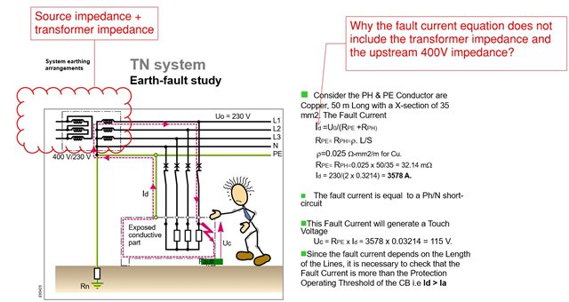
Why the fault current equation does not include the transformer impedance and upstream 400V impedance?
In principle it should (BS 7671 talks about the impedance of 'the source' (411.4.4) which would include the windings and a proportion of the upstream impedances). It's often approximated to 'the transformer winding' on the assumption that the HV side of the national grid has in effect an almost infinite amount of power available to it, so the effective impedance is negligibly low and due to the step-down effect of the transformer the effect of impedances on the primary side is less Ohm for Ohm than on the secondary side. BTW the 400V/230V designation is referring to the star arrangement of the secondary windings - 230V L-N but 400V between different lines - the primary voltage is usually far far higher - typically 11kV or 33kV in the UK - so the turns ratio is quite large.
If you had a small transformer (e.g. one for 110V tools) fed from the LV system, you'd certainly need to take account of the upstream impedances and %age impedance of the transformer to get anything like accurate results.
I suspect what you're seeing is a textbook example of what happens in schools - first teaching a simplified version and only later adding in a few complexities. (Like at primary school 'you can't take a larger number away from a smaller number'; but in secondary school saying, that's not quite right and introducing negative numbers).
- Andy.
The "symbols" do not align with BS 7671 and associated standards.
The first expression for fault current for a fault to cpc or exposed-conductive-part is incorrect, as AJJewsbury says it normally accounts for the external source impedance. The expression is usually written in the UK as follows:
If = CU0/(Ze+R1+R2)
where:
If is the fault current
C is a correction factor to take into account the maximum or minimum voltage. We choose either C=Cmax or C=Cmin depending on what we are trying to calculate, to obtain worst-case conditions. For public LV supplies according to the ESQCR in the UK, Cmax = 1.1 and Cmin = 0.95. As an example, Cmax would be used to obtain maximum prospective fault current, along with assessing touch-voltage (A722.3 in BS 7671), whereas Cmin would be used when calculating acceptable earth fault loop impedance for protective devices used for automatic disconnection of supply (Reg 411.4.4 of BS 7671).
U0 is the nominal voltage Line to to Earth.
Ze is the external earth fault loop impedance (source impedance) outside the installation.
R1 is the resistance of line conductor between the origin and the point of fault.
R2 is the resistance of cpc between the origin and the point of fault.
Why is Cmin not 0.94?
It's not because it says so in BS 7671 (but it does) ... the initial place voltage factor was introduced is BS EN 60909, and in particular BS EN 60909-0:2016 (Clause 5.3.1 and Table 1). The use of Cmax of 1.05 for supplies with permissible upper variation of +6 % and Cmin of 0.95 for supplies with a permissible lower variation of - 6 % is given in the paragraph just before Table 1 in the standard:
If there are no national standards, it seems adequate to choose a voltage factor c according to Table 1, considering that the highest voltage in a normal (undisturbed) system does not differ, on average, by more than approximately +5 % (some LV systems) or +10 % (some HV systems) from the nominal system voltage Un.
So, it's a "rule of thumb" based on a "near enough statistically" explanation.
The "rule of thumb" has been confirmed for use in PD IEC 50480:2011 and also for use in BS 7671 since BS 7671:2008+A3:2015.
You could use 0.94 in the UK for public supplies, I suppose, but this would be erring even more on the side of caution.

Seconded - the (hidden) assumption is that the transformer is a high power unit, capable of providing a short circuit current so high that it's extra impedance is small enough to be safely ignored.
That is probably true if it is a megawatt sized lump sitting on the ground, as the voltage drop at the transformer at normal full load will be a few percent ( full load currentt is 1MW/ 3 per phase = 330000watts at 230V - call it 1.4kA per phase) , so at your 3kA fault, your assumption that 115V is dropped in the phase, 115V in the CPC needs to be corrected to more like 100V in the CPC , 100V in the phase, and the transformer output droops from 230V to more like something between 200 to 210 volt or so, for the short time until the fault clears.
In terms of touch voltage, the risk is more or less the same so the simpler estimation method is good, and by over-estimation, errs on the side of safety in any case.
Of course if the transformer was a 'pole-pig' 50kVA unit on a wooden pole at the end of a long HV line to a small place in the country, then the transformer impedance would be 20 times higher and very noticeable, and the voltage droop on the primary 11kV supply line may also have a noticeable effect and for a truly complete model all this really needs to be included.
Do you need a complete model, or just one that gives an estimate erring on the side of safety ?
Mike
Thank you.
You could use 0.94 in the UK for public supplies, I suppose, but this would be erring even more on the side of caution.
Well, yes but it would at least be consistent with the pretend permitted voltage range of +10%/-6%.
It just raises the question of why then is Cmax not 1.09?

Well, yes but it would at least be consistent with the pretend permitted voltage range of +10%/-6%.
But they are different things in a way - for fault loops we're using the impedance of the entire loop - so the voltage is really that of the source (Uoc in old money) whereas the permitted voltage range is at the consumer's supply terminals, so has to include voltage drop in the supplier's lines. To use Ze and the voltage at the consumer's end would be to double-count the impedance of the supplier's lines (if under different conditions).
- Andy.
Well, yes but it would at least be consistent with the pretend permitted voltage range of +10%/-6%.
It just raises the question of why then is Cmax not 1.09?
Rules of thumb are not an exact science, they also incorporate the experience of the engineers proposing them.
In the UK, we often see, for great lengths of time, supplies at the "higher end", less so at the "lower end" - the statistics simply support the rule of thumb, and it doesn't really need to be more complicated than that.
Ok but "worst-case conditions" are not rules of thumb.
But in this case, the "worst case" is described by selecting, as appropriate, either Cmax or Cmin. For public supplies, you are not asked to determine the value to use for either Cma or Cmin, they are given to you in BS 7671 (and other standards).
Similarly, it could be argued that in some cases the 0.8 factor in the formula on page 410 of BS 7671 for max measured earth fault loop impedance isn't "worst case", but you are given it, along with the value to use for Cmin in the formula.
We're about to take you to the IET registration website. Don't worry though, you'll be sent straight back to the community after completing the registration.
Continue to the IET registration site
