Bonding maximum resistance

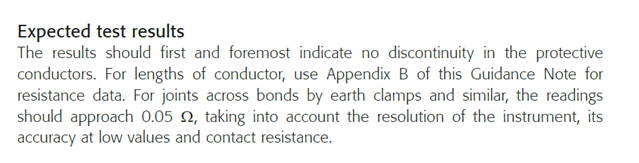
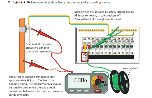
Apprentice electrician here and I would really like help on clearing up a confusion about bonding. I'm coming towards the end of my apprenticeship and have always been told that the maximum reading for a bonding to water and gas is 0.05ohms. I have been fine with this for the last 2 years but have this weekend been confused as GN3 and 7671 doesn't actually state this. Any help clearing this up you be amazing thank you. I know why we bond and what it is used for it's just where the 0.05 comes from. 

  • The 0.05 Ohms is merely a test of the connection of the conductor to pipe, i.e. the clamp joint.

    It is a value for a satisfactory near negligible resistance of the joint.

    It is not the resistance of the main bonding conductor from one end to the other - which is not a consideration.

  • It was also confused by some earlier editions of GN 3 which suggested a particular value (0.1Ω I think) for the overall resistance of a bond (e.g. from pipe to disconnected end at the MET) - the idea being if you got this value (or lower) it could be deemed satisfactory without any further ado. It did seem to get misinterpreted though - as many read it as a requirement that it should always be ≤0.1Ω rather than you needed to do some calculation (based on conductor length & c.s.a) to decide if the value obtained was reasonable if you had a higher reading. As you've already noted, BS 7671 only specifies min c.s.a for bonding conductors - there's no requirement as to their length or resistance - so higher readings may well be perfectly acceptable, indeed unavoidable, in some situations.

       - Andy.

  • but have this weekend been confused as GN3 and 7671 doesn't actually state this.

    Others have already pointed you in the right direction, but I'll see if I can provide a bit more information.

    BS 7671 does not put a specific limit for main bonding conductors (although one is available via formula for supplementary protective bonding).

    However, GN3 DOES include some guidance on what to expect when testing:

    • A suitable reading based on the expected conductor resistance per metre multiplied by the approximate length in metres
    • effectiveness of a "bonding clamp" of 0.05 Ω 

    So, the value of 0.05 Ω is mentioned, but as a guide for effectiveness of the connection of the conductor to the bonding clamp. Have a read on pages 60 to 62 of the 9th Edition. In particular, page 62 "Expected results":

    Put in pictures, the 0.05 Ω is the maximum difference expected between the second measurement (dotted line on red lead, to the pipe) and first measurement (no dotted line on red lead, to the bonding clamp). The first measurement should be roughly (or less than) the length of the bonding cable from the MET (in metres) multiplied by the resistance per metre of the cable at 20 deg C in Appendix B to GN 3 - BUT the value may well be less than the overall "resolution plus accuracy" of your test instrument, which is where the 0.1 Ω suggestion comes in.

  • note another rule of thumb - 1mm2 of copper 1m long is 16 milliohms (cold - or more like 19 milliohms hot) so if you have a cross section  of 10mm2, the resistance per metre is 1/10 of this, but if you have a length of xx metrres, multi0ply by that. No need to reach for the tables.

    50 millioms, has more to do with allowing for the sort of error introduced by meter leads and scratchy  points of contact on slightly oxidized surfaces. In many ways a car battery and a headlamp bulb or car horn would be just as good as a continuity assessment in terms of checking that it can carry a representative fault current...

    If you actually need to measure a low resistance really accurately a 2 lead meter  is not  really the way - you need 4 wire test, where current is injected by one pair of wires in which you can neglect the voltage drop, while the voltage drop accross the resistance of interest is measured with another separate  pair of wires making contact nearby but not in the same place - the voltage measurement contacts are not carrying much current. This avoids being fooled by voltage drops in the leads and the effects of current crowding near contact points.

    Also at low voltage drops - less than half a volt say, metal/metal oxide layers form a crude semiconductor diode that can give an apparently higher resistance than if measured with a large enough test current to get a few volts dropped. 'No trip' Zs readings can often be a bit fruit machine because of this. A bigger meter (well one with a higher test current) is usually more accurate in such cases.

    Mike.

  • Has the verification process for protective bonding conductors been updated to necessitate the measurement of resistance values, as opposed to the previous method of a visual check and confirmation via a tick box? Tables are available indicating the expected resistance measurements for protective bonding conductors of different lengths. For example, assuming a conductor cross-sectional area (CSA) of 10 mm². The resistances are listed as follows for the corresponding lengths: 5 meters: 0.01Ω 10 meters: 0.02Ω, etc.

  • Has the verification process for protective bonding conductors been updated to necessitate the measurement of resistance values

    Expected results are not necessarily recorded results, although the forms in Appendix 6 are only guidance, so you can write an actual result, as well as a tick if you want to.

    As to what's expected ... which bonding conductors?

    Main - BS 7671 has no minimum value, so the "box" (noting Appendix 6) can just be ticked, but clearly we need to check we've no installation problems, damage or errors for initial verification. Similarly in periodic, no damage or degradation - hence the reading you're really expecting is the "limit" that achieves the "tick" but this is not firm.

    Supplementary protective bonding is VERY different (and always has been). It has a criterion to achieve a theoretical maximum touch potential, of either 50 V (if applied under Section 415) or 25 v (if applied under Section 710 or APEA Blue Book for filling stations)  for the expected fault current. Again, this is the criterion that gets the "tick".

    So no change, but a measurement has always been necessary for supplementary bonding, and a useful tool, and perhaps an indicator of a more experienced inspector, for main bonding.

    BS EN 50310 definitely has resistance measurement criteria also.

  • Supplementary protective bonding .... It has a criterion to achieve a theoretical maximum touch potential, of either 50 V (if applied under Section 415) or 25 v (if applied under Section 710 or APEA Blue Book for filling stations)  for the expected fault current.

    Isn't it based on the current required to open the protective device within 5s, rather than the expected fault current - which could (often should) be significantly larger? Larger currents may produce larger touch voltages (exceeding 50V or 25V), but balanced with reduced disconnection times.

      - Andy.

  • A test meter doing Giga ohms would be more accurate than an MFT doing Milli Ohms.  However outside of a lab enviroment I am not sure how practical it would be to do Giga Ohms testing. 

  • Thank you too everyone that has helped me with this. It has cleared a lot up with my knowledge. 

  • Thank you for this it explains it really well. I honestly think the cable length example for the 10mm at 25 metres being 0.05 should be removed as I think this is causing all lot of the confusion withing the trade. Thank you again.