Re: Insulation Resistence Testing

Re: Insulation Resistance Testing

This may seem like a stupid question, one that is probably abundantly clear, but it's baffling me. 

In a circuit where there is two way switching, the IR test requires that the switches need to be 'toggled. Therefore, the requirement to repeat the test.. Similarly with a circuit with intermediate switching, there is a requirement to operate the switches. 

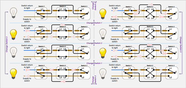
What is confusing me, (and I have drawn out the wiring diagrams by hand and the various combinations) trying to understand,as to how the switches should be operated and tested. 

i.e with two way switching - IR test, alternate switch on one switch and test, and alternate the 2nd switch and test....or IR toggle both switches and test. 

 i am assuming that on the first test uncertainty exists and there is no way of knowing whether  the circuit is off/on.

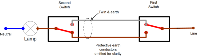
Does it matter if the circuit is connected via 3 core system - common in domestic setting where there is a single strapper and permanent line (PL) and switched line (SL) are via l1 and l2 or if it connected via 2 strapper system with PL from switch A  com and Sl from Switch B  Com. 

From my wiring diagrams and tracing it - it seems that with the single strapper system and the two way strapper system - switching works differently and the electrical flow is different. 

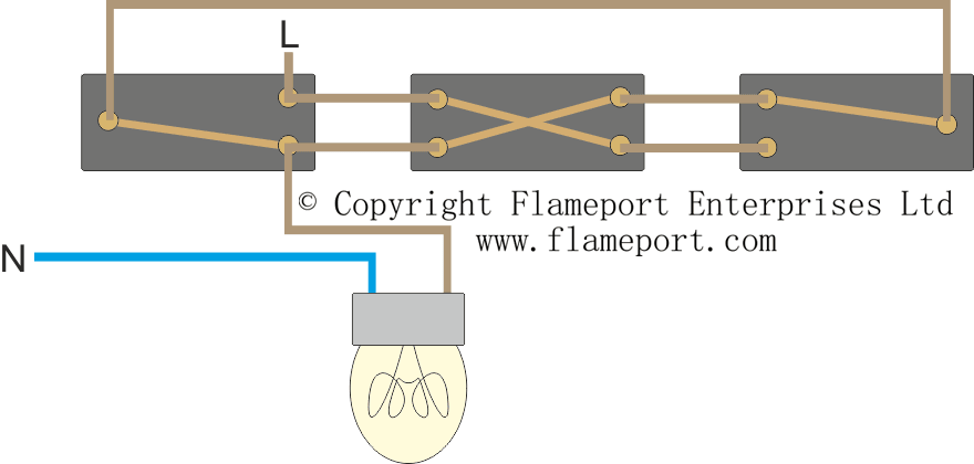
How would it be done, combinations with the intermediate switching?

sorry for the   long question..but want to be clear  as to the process. 

  • If you do the test as L+N in parallel to E, then the exam question, is are there any lengths of wire not tested in any switch positions .

    Now consider

    here a short to ground on any wire will be found if the bulb is in but if it isn't then in neither of the 2 off states then the bulb live  (here gry) wire will not be energised, and neither will the central (black) wire in one of the 2 'off' states. In the on state, all wires get tested.
    But how do we know - well test, flick one switch, test again.
    Now consider


    here again if the lamp is in the off states get tested. But in either one 'on' state, the unused path is not tested.  Here we need to either fit the lamp, or toggle both switches to be sure.
    Now intermediate switching is more complex. Here again there are 2 ways to wire, plus the intermediate crosses or un-crosses the laterals. At worse, again 2 switches must be operated to cover all cases.

    Note that other things like heating systems have similar untested branches depending for example on thermostat and timer states, but in practice where it is too hard to force the switch states, it is usual to inspect visually and then not worry too much. Very rarely you see things where for example a trip fires when a given heating zone comes on.

    Mike


    Acknowledgement to JW and DIY wiki for their pics.

  • Test in all combinations.

    SW1 SW2
    up down
    up up
    down down
    down up

    or

    SW1 SW2 SW3
    up up up
    up up down
    up down up
    up down down
    down up up
    down up down
    down down up
    down down down
  • Thank you for the replies. 

    I take Chris’s point that you could test through all the probable combinations. However, I was looking for a method to test all the conductors with the least minimal amount of test.

    With the Mapg1 reply, I am trying to process this. IS is being suggested that to cater for both types of wiring methods (1 strapper v 2 strapper system) the following should be done:

    Two way switching 

    sw1 sw2

    down down  

    down up 

    up up

    Intermediate switching 

    sw1 sw2 sw3

    down down down

    up down down

    up up down

    up up up 


    The above method should ensure that all the conductors are checked, regardless of the method of  system used.

    Is this correct??

    Thanks


  • This picture might help, that shows all the combinations for 2-way with intermediate switch ... it's from the EDA Product Knowledge series Wiring Devices and Controls:

  • It may relieve you to know that regardless of the no of intermediate switches, you only ever have to switch one to cover all that would have been covered in a system without intermediates, the number of tests  is not  n! where n is the no. of switches.

    Mike

    ! Factorial notation explained

  • As others have said above, there are 8 combinations of switch position.

    However, for the purposes of insulation resistance, I would assert it's not necessary to do all 8 combinations

    you only ever have to switch one to cover all that would have been covered in a system without intermediates

    Possibly true of the wiring, but is it true if you want to check there isn't a fault in an intermediate switch or either 2-way:

    • In any combination where the lamp would be on (check for continuity between "switch supply" and "switch return to light"), all live conductors are effectively "in-circuit", a test of one live conductor to PE tests all live conductors to PE.

    • With a single intermediate switch, you will then need to check 2 positions of the 2-way switches for the "off" state with the intermediate in one position, to check insulation between "Switch supply" to "switch return" - this proves no shorts in:
      • Line to line conductors in wiring throughout
      • insulation resistance in both 2-way switches is adequate C to L1, C to L2 and L1 to L2.
      • Intermediate switch insulation resistance for one position is adequate
    • And finally, switch the intermediate switch to the other state, and select an "off" position using the 2-way switches, check insulation between "Switch supply" to "switch return" and this proves adequate insulation resistance for the other combination of 2-way switch.

    So, I think 1 "on-state" and three "off-states" will do the trick for a single intermediate switch. Last step repeated for each intermediate switch if there is more than one.

  • If you are only looking for faults to ground in the wiring to the switch terminals, and not operation under load, then adding any number of intermediate switches only increases the no of tests by one, over and above the no of tests that would have been needed for the chosen style of 2 way circuit without any intermediates , as then all 4 terminals in all intermediate switches on the path are energized in one or another test.

    I agree actual switch operation is not tested, but IR does not do that anyway, even single pole.

    It is very hard to envisage a credible fault path to earth within a plastic switch body that occurs with the switch crossed that does not occur with it un-crossed or vice versa.

    Once under power you should probably still test that all switches operate the lights as expected, unless the switch maker has done that at the factory, but even that only needs to be done in pairs, not all combinations, to exercise all moving contacts. By the time you have half a dozen intermediate switches, this is worth thinking about hard.

    Mike

  • It is very hard to envisage a credible fault path to earth within a plastic switch body that occurs with the switch crossed that does not occur with it un-crossed or vice versa.

    Switches that are wet inside and appear dry outside ... sadly if you don't catch it at IR test, it makes a lovely black mark up the wall.

    The first time I ever encountered this was back in the late 1970s, when my Dad asked my Mum to wipe the kitchen light switches over before refitting them after tiling. Unfortunately, the "wipe over" was done after first soaking the switches in sugar soap !

    The fault path could also be L to L ... BS 7671's initial position is that insulation resistance is all live conductors.

  • Ha! - well with sugar soap in the works all bets are off I think.  In a similar vein  have seen a normal (single pole) switch pass IR and then make  most impressive bang  when turned off due to wet plaster, or it may have been polyfilla,  giving off steam having got trapped somewhere that was not a tested path,,,

    However I's pretty sure that it is also the BS7671 view  that L+N to E testing is a perfectly acceptable way to do an insulation test and perhaps more sensible if fixed loads are already in place as then they get tested at the same time. It depends rather, personally I think there are more positive ways to find L-N and L-L faults without hurting anyone, whereas missing earths and faults to earth may be missed for years.

    More relevant is the fact that things with very many states, like heating and ventilation  systems in larger buildings are very hard to test in situ and be confident sure that all wiring paths have been covered.

    Mike

  • However I's pretty sure that it is also the BS7671 view  that L+N to E testing is a perfectly acceptable way to do an insulation test

    Disagree, for initial verification (including additions, alterations and arguably repairs depending on what has been repaired) ... the "go to" for initial verification is still 'between live conductors and between live conductors and the protective conductor connected to the earthing arrangement' (643.3.1) prior to the connection of equipment that might be damaged by such tests (643.3.3).

    Only after these tests have been performed, can the 'L+N to E' test be performed.