
I had an email this morning from the IET telling me that a Draft for Public Consultation has been published for Amendment 3 to BS 7671.
Details here electrical.theiet.org/.../
JP
I had an email this morning from the IET telling me that a Draft for Public Consultation has been published for Amendment 3 to BS 7671.
Details here electrical.theiet.org/.../
JP
Just based on Mark Cole's video....
OK, I'm confused already (I know, with me it's easily done...)
First thought - does this cover my simple PV system? In the grand scheme of things power only flows one way - backwards - from the Inverter to the CU. So not bi-directional? At a more detailed level the inverter does draw a little power overnight (just to keep the grid fail monitoring and general logging going) - would such tiny amounts (<1W from memory) count as making it bi-directional?
Second thought was for inductive (or indeed capacitive) loads - with a power factor other than unity (1.0) - if I've understood AC theory correctly, some power flows backwards during part of each cycle (hence the difference between W and VA, or the so-called "wattless current") - so is it allowable to add up instantaneous power over a period (allowing some backward power to be cancelled out) before deciding whether the overall power flow is bi-directional or not? if so, how long? A single cycle, or perhaps longer - e.g. would a machine that mostly drew power, but occasionally used say re-generative breaking to push waste power back into the grid, count?
Maybe I've missed something somewhere (or forgotten what I already knew - that seems to happen more often these days) - but what are the physical effects we're trying to avoid with all this? If it's purely down to power flow it presumably doesn't matter if voltage is left on the "load" terminals when the device is open (otherwise we'd have caveats for devices connected in parallel or back-feed situations), and normal current flows in both directions anyway (on each half cycle), so nothing can be polarity sensitive in the conventional sense (like semiconductors) or the way an arc breaks.. . or can it?
- Andy.

.Ah, something's returning... . was it something to do with the way T buttons are wired? Make the wrong assumptions and the test circuit connects the supposedly dead side to the supply with the device open and the button pressed?
Hi Andy
There are several things it tries to address.
Power on the load side of a circuit could burn out the circuitry of lets say an RCBO as it in effect has an inwards side and an outwards side. ie Supply and Load
Also circuits back feeding onto the grid from micro generation like Solar PV or Car2Grid (other names are available)
I've dismantled quite a few to see what the directional dependant features are.
At the outset the T button was on my list of concerns - most seem to use 2x 4.7k 1206 resistors in series. These are rated 0.25W each. So they're 1/10th the necessary rating, which is absolutely fine if the RCD interrupts them but not okay if it can't.
Curiously several RCBOs - especially budget ones like Fusebox - have the T button arranged between L on the incoming side and N on the outgoing side. This is contrary to the little diagram on the side of the device. Of course this means that in those cases the T button would be fine. But in e.g. Hagers miniature RCBOs it wouldn't be - Hager are single pole so they couldn't pull this trick.
In terms of ability to withstand being powered from downstream - I've not found any that should have too much problem as they all have quite robust input protection. However I if this circuit did develop a fault then it's protected by the fault coil on the MCB function - whereas if it was fed downstream it wouldn't.
But then vast majority of these applications the downstream has e.g. ROCOF protection.
But there's a big unresolved issue - what should be the overarching principles for protection of generators in these applications? The regs - even in Part 8 - just don't give a satisfactory treatment. Worse still most inverters have very poor MIs when it comes to the protection of their terminals - what is the prospective fault current at a PV inverters terminals? The manufacturer doesn't usually know.
I'm not sure why this is being billed as an emergency amendment. Where's the evidence to back up that this is causing sufficient risk? Presumably if it was a risk then there would be evidence of incidents stemming from it given people have been connecting PV systems to RCBOs for a very long time - maybe the hazard is a novel one due to islanding mode?

does this cover my simple PV system?
More than likely, yes.
So not bi-directional?
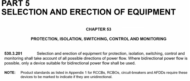
Well, no, bi-directional. A fault in that circuit be fed from either side, and in theory, power could flow either way ... most importantly, even if only for a (potentially very short) time, power will be available on live conductors on both sides of the device even if it operates (with an RCD, say, even when the test button is pressed).
does this cover my simple PV system?
More than likely, yes.
So not bi-directional?
Well, no, bi-directional. A fault in that circuit be fed from either side, and in theory, power could flow either way ... most importantly, even if only for a (potentially very short) time, power will be available on live conductors on both sides of the device even if it operates (with an RCD, say, even when the test button is pressed).
But whilst the fault current from the grid is typically in the kA region, the maximum short circuit that an inverter can feed is mentioned in it's datasheet and typically <=32A.
If you look in BS EN 61009-1 at the tests that are different for bi-directional devices - they are only tested differently to unidirectional devices for the detemination of Isc and Icn [9.12.11.4 b)1) & c) respectively].
It follows that if you know the maximum short circuit current that can flow upstream through a device is < 1.5kA then it makes no difference.
Interestingly bi-directional devices aren't - according to EN 61009-1 - actually functionally tested in all 4 quadrants other than for Isc and Icn.
Well, no, bi-directional. A fault in that circuit be fed from either side, and in theory, power could flow either way ... most importantly, even if only for a (potentially very short) time, power will be available on live conductors on both sides of the device even if it operates
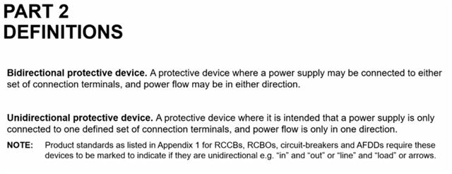
That seems to be a different definition again - power being available (i.e. voltage present?) isn't quite the same as power flowing, especially when the device is open. That would seem to catch cases where there's individual protection to parallel conductors of the like shown in appendix 10 - with the typical arrangement of nothing but loads on the load end, I'm not sure many would have thought that it constituted bi-directional power flow - especially for the supply end devices, yet when the first device opens there'll be voltage on both sets of terminals.
- Andy.
We're about to take you to the IET registration website. Don't worry though, you'll be sent straight back to the community after completing the registration.
Continue to the IET registration site