
I had an email this morning from the IET telling me that a Draft for Public Consultation has been published for Amendment 3 to BS 7671.
Details here electrical.theiet.org/.../
JP
I had an email this morning from the IET telling me that a Draft for Public Consultation has been published for Amendment 3 to BS 7671.
Details here electrical.theiet.org/.../
JP
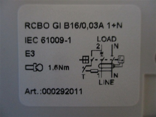
When a residual current is detected by the current transformer, a signal is sent to the electronics from the secondary winding, which in turn opens the gate of the thyristor and allows current to flow to the solenoid. This causes the solenoid to operate resulting in the operation of the switching mechanism and opening of the contacts which interrupts the current flow.
The important thing here is that once a signal enters the thyristor gate and activates the device, it will continue to pass current until the voltage drops below a specific level. In the event of an earth fault or using the test button, the RCBO will trip but there will still be a voltage present on the load terminals from the PV inverter resulting in current flowing through the thyristor and the solenoid being activated for an extended length of time.
I've been pondering this - and I'm not sure I'm convinced now. If I recall correctly from by PE mag days, the thyristor will turn off as soon as the current through it drops to zero - and as RCDs operate on AC that's every half cycle. So it can only overheat if the electronics continue to trigger the gate, which should only happen if there's an imbalance in the toroid.- which now there can't be as the only load on the mechanism side of the open contacts is the RCD electronics etc themselves - and that current (if the diagram is correct) should be returning through the toroid.
e.g. adding the return current to the diagram (orange arrow) we get:
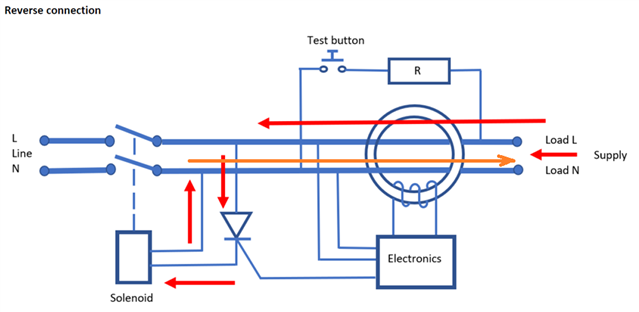
So at the moment I'm thinking that the electronics/thyristor/solenoid are in no more danger of overheating than they would be in normal service with the contacts closed - which hopefully is pretty negligible. Or I've missed something (again...).
- Andy.
When a residual current is detected by the current transformer, a signal is sent to the electronics from the secondary winding, which in turn opens the gate of the thyristor and allows current to flow to the solenoid. This causes the solenoid to operate resulting in the operation of the switching mechanism and opening of the contacts which interrupts the current flow.
The important thing here is that once a signal enters the thyristor gate and activates the device, it will continue to pass current until the voltage drops below a specific level. In the event of an earth fault or using the test button, the RCBO will trip but there will still be a voltage present on the load terminals from the PV inverter resulting in current flowing through the thyristor and the solenoid being activated for an extended length of time.
I've been pondering this - and I'm not sure I'm convinced now. If I recall correctly from by PE mag days, the thyristor will turn off as soon as the current through it drops to zero - and as RCDs operate on AC that's every half cycle. So it can only overheat if the electronics continue to trigger the gate, which should only happen if there's an imbalance in the toroid.- which now there can't be as the only load on the mechanism side of the open contacts is the RCD electronics etc themselves - and that current (if the diagram is correct) should be returning through the toroid.
e.g. adding the return current to the diagram (orange arrow) we get:
So at the moment I'm thinking that the electronics/thyristor/solenoid are in no more danger of overheating than they would be in normal service with the contacts closed - which hopefully is pretty negligible. Or I've missed something (again...).
- Andy.
closed
Yes it would normally interrupt at the next half cycle.
Also it's been tested for an inductive load fault at 0.7 pf so the thyristor will be able to handle substantial back EMF too.
However if you've got an inverter in a fault state that starts feeding DC, or a line-commutated inverter that depends on its load to get back to zero crossing then you might have a problem. A 1kVA line-communtated inverter would need to dump upto around 10J before it can zero cross.
That said, if an installation has a line-communtated inverter it would become apparent quite quickly that it's not compatible with the RCBO. Ultimately we're supposed press the T button regularly. My main worry with this ammendment is that it's going to trigger a lot of inappropriate C2s from people interpreting a lack of protection and therefore potentially dangerous when in reality the risk is in many circumstances there's still fault and overload protection so it would tend to be a C3.
I'm not sure how the proposed wording can be changed to address that - the GN2&GN6 are the place for that commentary. But we know very well that whenever there's a national departure of this kind there's a guarantee that people will over-react.
Having seen no end of incompetent board changes to address inappropriate C2s on plastic boards that ought to have been C3 - I'm sceptical. At the same time there's some very sensible points here which Graham Kenyon is rightly highlighting and I agree with him that they should be addressed.
It's very difficult to choose wording which is objective and there's nothing Graham and his colleagues on JPEL/64 can do about people willfully misusing the regs - they have to assume people are competent even though clearly not everyone is.

It's very difficult to choose wording which is objective and there's nothing Graham and his colleagues on JPEL/64 can do about people willfully misusing the regs - they have to assume people are competent even though clearly not everyone is.
Yes, but when you have BEAMA giving strongly worded advice;
Along with what looks like an emergency amendment to 7671 being rushed through with the only focus being on the bidirectional issue, one can hardly fault lads inspecting installations from jumping to the conclusion that this is an important safety matter worthy of a code 2!
Nor indeed, is it reasonable to contend that lads at this level would have the technical understanding necessary to make informed decisions other than what is embedded in the messaging.
So one would hope ESF or the like will be quick of the mark to guide the troops in this case.
Yes, but when you have BEAMA giving strongly worded advice;
Thats what worries me, and what I find curious.
If this is the serious issue that report suggests then why aren't their any case studies? Surely there's countless examples of exactly this? I was involved on a policy side with the requirements for non-combustable DBs - which was very sensible and has undoubtedly saved lives - but it was based in good evidence and the LFB were excellent in their provision of data and case studies.
My interest in this particular ammendment is because I am responsible for a product used right in this part of a circuit - and we have to withstand OVCIV due to the transients. I'm of the school of being candid about hazards so that as engineers we can work them.
It looks like someone has identified a problem. But there's no candour about the scope of it. It might well affect bidirectional RCCBs which depend on SCPDs. It might well affect adjustable speed drives but there's nothing in the BEAMA note about that or the scope this ammendment.
If an unidirectional RCBO has spent the last 10 years on a G99 compliant PV installation and had the T button pressed under reverse load countless times then in view of the fact that the inverter has loss of mains protection and the RCBO must accept a 6kA fault through a heavily inductive load anyway then whilst I completely agree its a C3 I can't agree that it's a potentially dangerous installation.
If BEAMA have information that would disabuse anyone who feels that way then their being very closed about it.
I'm worried that we've got an ammendment without a good treatment of the problem. And a 10 page report of which 9 pages are covers, contents, summary and diagrams for anyone who doesn't know what a consumer unit looks like isn't a treatment of the problem.

- which now there can't be as the only load on the mechanism side of the open contacts is the RCD electronics etc themselves - and that current (if the diagram is correct) should be returning through the toroid.
Unless the test button remains pressed in which case the imbalance remains and the thyristor (or I guess it could be a triac in some designs) is fired again?
Unless the test button remains pressed in which case the imbalance remains and the thyristor (or I guess it could be a triac in some designs) is fired again?
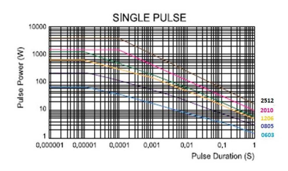
Of the units I've pulled apart I think every one of them has 2x 2.7k 1206 resistors in series [giving 5.4k and therefore 42mA]. A 1206 resistor is typically rated to 250mW but some go up to 1W.
So for continuous pressing the resistors are grossly undersized - at 230V this would dissapate 4.9W in each <= 1W resistor! So they clearly depend on the breaker opening in order to get away with this. I have a feeling these are 0.75W's with a rating to 2.5x rated voltage for short term overload so they can take 4.68W for 5s which is still what Sir Alex Ferguson would call squeeky bum time.
Should note however that manufacturers usually take one side of the test button to the metalwork on the solenoid. For many this means that the button is between Lin and Nout - for others it's between Lout and Nout depending on if the solenoid is before or after the contactor. One thing i've noticed is that the diagram on the side of the devices is only a functional description and typically bears little resemblance to internal operation.
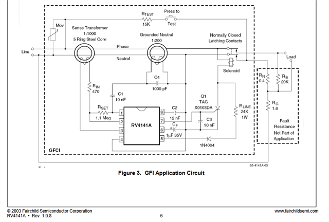
What I've found particularly interesting is that most of these devices use one of a handfull of GFCI controller's IC such as the popular but end of life RV4141 from Fairchild Semiconductor [now ON Semiconductor]. I mention this because on all of the application notes I've seen from ON & TI who dominate this market is that they all have the electronics on the incoming side - whereas RCBO manufacturers prefer to put the electronics on the outgoing side. The image below is from the bottom of pg 6 to the RV4141A datasheet. [this example circuit probably only meets Type AC and not A due to core saturation combined with the fact it only works on one half cycle, and it's configured for UL 943]
Edit: one consequence that has just occured to me - If you lock off and RCBO following safe isolation then someone comes along and presses the T button - this would on some DP devices connect Nout to Lin via 5.4k of resistance. This would come as a very nasty surprise to a person working on the isolated circuit.

Perhaps this transient rating data from Vishay will re-assure you that it needs to be fast, but so long as it is then all is well - unless the mechanism jams.
Mind you I have heard of ones that did not trip and then went off with a bang. And any motor or capacitive load that provided significant voltage hold up after contact opening might not be that great either.
'continuous' in this context means a succession of repeated (but widely spaced) pulses
![]()
Data from most other makers of SMD resistors are broadly similar - the time constant kink at 100-300ms is set by the ceramic substrate of the resistor and any longer term trend has more to do with the PCB solder pad size and cooling that way. Note that for high resistor values, a flash-over voltage limit may crimp the higher power/short pulse end of the curve.
Oddly TE connectivity publish data for theirs for lone pulses that disagrees and shows no slow kink - this suggests a non repeating pulse can be quite a bit higher in amplitude. This family of lines seems to be near, but not quite, constant energy - so closer to an I2t type rating.
Regards, Mike
edited for unclear grammar.

Very interesting point about RCBOs, the test button is held down on a Locked off RCBO, can link Nout to Lin through a 5.4k ohm resistor? calls into question the robustness of current safe isolation practices.
Although many modern RCBOs seem to have a 3rd contact that breaks the test circuit when the device is opened.
e.g.
- Andy.
calls into question the robustness of current safe isolation practices.
Yes it doesn't sit well with me. On the one hand the resulting current flow from this in addition to skin resistance would be unlikely to cause injury on it's own. On the other had if you got a shock of this whilst e.g. on a ladder then it could result in death or serious injury.
Although many modern RCBOs seem to have a 3rd contact that breaks the test circuit when the device is opened.
Yes, i wonder if any of the one's i've dismantled achieve this but it's not apparent because when you dismantle a RCBO then springs fly everywhere. I metered one and it certainly didn't isolate the T button - and IEC 61009-1 appears silent on the question too - I would have expected it to require e.g. the insulation test in open state to be performed with all controlls that aren't capable of locking in the most adverse state.
Perhaps this transient rating data from Vishay will re-assure you that unless the mechanism jams, it needs to be fast, but so long as it is then all is well.
Yes the transisent rating is far higher than the short term overload rating - which is based on 5s. So no doubt if the contacts open then it's not an issue - save for those that are entirely downstream of the contacts in the event of being energised from the load terminals. That said a grid tied inverter would interrupt power within 5s too so that shouldn't be a problem either.
I think it is becoming clear that the issue is DC current depriving the thyristor/triac of the opportunity to switch off - just a shame the BEAMA report didn't say that. I think the overall solution of having Type A's which interrupt downstream of the triac is a pragmatic one as opposed to the more costly option of requiring Type B's. But two obvervations in this respect:
1) Bidirectional RCBO's already exist - some of these might not be compatible with this arrangment because the requirement for an RCBO to be bidirectional is that it can interrupt a fault current to it's Ics rating. I'm not sure that knowing an RCBO can reliably interrupt a 6kA fault fed from an inverter is particularly useful when we know the inverter's short circuit current is <40A.
2) The new Bidirectional RCBO's appear to place the electronics on the "supply" side. This is perfect for the scenario where you've got a grid tied inverter because you know the DNO's supply is AC due to the big 50Hz transformer the DNO uses as opposed to the switching converter that the inverter uses. But it's a misnomer to call them Bidirectional - they are still directional in respect of how they behave in response to a fault with DC components.
Where can this go wrong?
1) An RCBO DB with new Bidirectional RCBO's goes into island mode, RCBO's other than the one for the inverter trip with an enormous bang because they've got their electronics pointing towards the inverter. This is a preventable problem but nobody see's it because we're all taken in by the idea that they're "Bidirecitonal". - Hopefully the RCBO protecting the inverter would trip first but we don't know that because there's no selectivity between two 30mA RCBO's, and in any case the inverter could very reasonably be on an MCB.
2) An RCBO that is Bidirecitional according to BS EN 61009-1, but not according the assumptions made in this ammendment is used. This is less likely because all the prominent manufactuers are pivoting towards this, but the "manufacturers" are often in fact "importers" who don't have a clue what's inside their product and depend upon a test report. So if you go to the far east and ask a manufacturer to make you an RCBO that's bidirectional - and have IECEE test report to that effect - then you'd be quite reasonably placing a bidirectional product on the market and an electrician will quite reasonably depend on that to protect an inverter. Without a national departure in BS EN 61009-1, then once people forget about this ammendment and move onto the next shiny thing accidents are going to happen.
3) RCBO's used on off-grid systems.
What's the solution?
I think the focus should be less on the "bidirectional" issue and more on ensuring that any RCBO used in conjuction with an inverter is declared in the MI's to be suitable for use with inverters subject to the inverter's own MI's declaring compatibility with Type A RCBO's. This avoids getting bogged down in trying to get a national departure in BS EN 61009-1 - because the MI's would be over and above. It also avoid the absurdity that the new "bidirectional" RCBO's may not be compatible with inverters if connected in reverse. This creates a pragmatic middle ground between inexpensive Type A's and Type B's which are largely unnescessary in these applications.
I think it is becoming clear that the issue is DC current depriving the thyristor/triac of the opportunity to switch off
I suspect I'm not following your thinking here ... are you suggesting the PV inverter may start generating d.c.once the normal mains is removed?
- Andy.
We're about to take you to the IET registration website. Don't worry though, you'll be sent straight back to the community after completing the registration.
Continue to the IET registration site