
I had an email this morning from the IET telling me that a Draft for Public Consultation has been published for Amendment 3 to BS 7671.
Details here electrical.theiet.org/.../
JP
I had an email this morning from the IET telling me that a Draft for Public Consultation has been published for Amendment 3 to BS 7671.
Details here electrical.theiet.org/.../
JP
Just based on Mark Cole's video....
OK, I'm confused already (I know, with me it's easily done...)
First thought - does this cover my simple PV system? In the grand scheme of things power only flows one way - backwards - from the Inverter to the CU. So not bi-directional? At a more detailed level the inverter does draw a little power overnight (just to keep the grid fail monitoring and general logging going) - would such tiny amounts (<1W from memory) count as making it bi-directional?
Second thought was for inductive (or indeed capacitive) loads - with a power factor other than unity (1.0) - if I've understood AC theory correctly, some power flows backwards during part of each cycle (hence the difference between W and VA, or the so-called "wattless current") - so is it allowable to add up instantaneous power over a period (allowing some backward power to be cancelled out) before deciding whether the overall power flow is bi-directional or not? if so, how long? A single cycle, or perhaps longer - e.g. would a machine that mostly drew power, but occasionally used say re-generative breaking to push waste power back into the grid, count?
Maybe I've missed something somewhere (or forgotten what I already knew - that seems to happen more often these days) - but what are the physical effects we're trying to avoid with all this? If it's purely down to power flow it presumably doesn't matter if voltage is left on the "load" terminals when the device is open (otherwise we'd have caveats for devices connected in parallel or back-feed situations), and normal current flows in both directions anyway (on each half cycle), so nothing can be polarity sensitive in the conventional sense (like semiconductors) or the way an arc breaks.. . or can it?
- Andy.

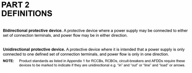
The proposed amendment BS 7671:2018+A3:2024 follows a BEAMA technical bulletin concerning connection of unidirectional and bidirectional protective devices such as Circuit-Breakers, RCDs and AFDDs to power supplies, such as PV inverters, Electrical Energy Storage Systems (EESS) and Vehicle to Grid (V2G) electric vehicles (EV).
The issue highlighted in the BEAMA technical bulletin is regarding the ‘line’ and ‘load’ convention. The relevant product standards, such as BS EN 61009 require protective devices such as RCBOs to be marked to indicate ‘line’ and ‘load’, or ‘in’ and ‘out’. The concern is that if a power supply, such as a PV inverter is connected to the ‘load’ or ‘out’ terminals of a unidirectional RCBO, parts of the electronic circuit can be damaged.
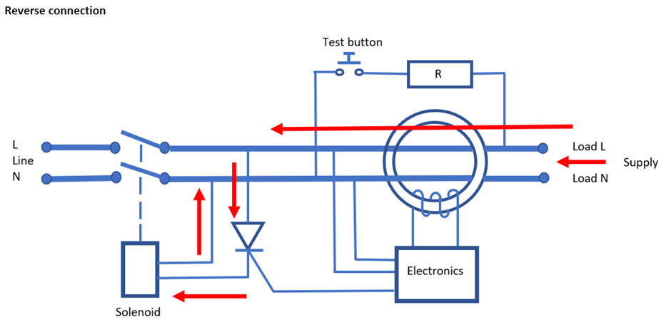
When a residual current is detected by the current transformer, a signal is sent to the electronics from the secondary winding, which in turn opens the gate of the thyristor and allows current to flow to the solenoid. This causes the solenoid to operate resulting in the operation of the switching mechanism and opening of the contacts which interrupts the current flow.
The important thing here is that once a signal enters the thyristor gate and activates the device, it will continue to pass current until the voltage drops below a specific level. In the event of an earth fault or using the test button, the RCBO will trip but there will still be a voltage present on the load terminals from the PV inverter resulting in current flowing through the thyristor and the solenoid being activated for an extended length of time.
The thyristor and solenoid are short time rated components, any delay in interrupting the supply will result in damage to these components rendering the residual current detection inoperable. The design of RCBOs will vary between manufacturers, the thyristor and solenoid are one example of the components that can become damaged.
Where Moulded Case Circuit Breakers (MCCBs) are reverse connected, their arc extinguishing/short-circuit characteristics could be impaired.
The diagram below shows reverse connection of a unidirectional RCBO.
I hope this is helpful.

I hope this is helpful.
Michael, it is indeed. :-)
What about ordinary (domestic/commercial/light industrial) MCBs?
I ask because the most suitable piece of roof of my house is adjacent to a DB, which is supplied through an MCB - no need for an RCD and the other circuits have RCBOs. If the wiggly amps can come back down those cables and back through the MCB for onward consumption elsewhere in the house (or further away), happy days!
(My MCBs are labelled, "2" and "1" for supply and load respectively, so all seems well.)
What about ordinary (domestic/commercial/light industrial) MCBs?
Domestic MCB's typically don't have any electronic controls in them unlike some MCCB's, but always check the MI's because someone is likely to have made one.
One thing that was missed [or not deemed relevant] by BEAMA and by Michael's excellent article in Wiring Matters [https://electrical.theiet.org/wiring-matters/years/2024/99-march-2024/bidirectional-protective-devices/] is that whereas RCBO's&RCD's may use a variety of terms to indicate directionality, an MCB/MCCB must use the arrow indication as the relevant standards for those devices dictate that an arrow must be used. I think it's worth noting.
The thyristor and solenoid are short time rated components, any delay in interrupting the supply will result in damage to these components rendering the residual current detection inoperable. The design of RCBOs will vary between manufacturers, the thyristor and solenoid are one example of the components that can become damaged.
This is very interesting. Although I've noticed that almost every RCCD on the market is bi-directional whereas RCBO's typically aren't - so my understanding from 61008-1 and 61009-1 was that when interrupting a fault of >1.5kA it would cook the electronics. But this got me thinking - RCCD's usually meet short circuit current withstand by coordination with a SCPD, and 61008-1 provides for this. But that particular test is performed with the SCPD upstream of the RCCD [See figure 7 BS EN 61008-1:2012+A12:2017] - the opposite of how we normally connect them.
I wonder how they would perform if that test was turned on it's head? Maybe RCCD's aren't quite as bidirectional as their MI's suggest?

I hope this is helpful.
yes much so - thank-you!
Which then begs the question about other situations where the load side doesn't immediately become dead as soon as the device opens. E.g. feeding capacitive or inductive loads, or even decent sized motors that may gradually spin down over many seconds, acting as an impromptu generator. We've had many reports over the years of RCD testers being fooled into thinking RCDs haven't opened or opened too slowly by the effects of connected loads. If 0.5s PV disconnection times may be too long. a lot of these other sources presumably must be contenders too?
- Andy.
So in a nutshell this is really aimed at any devices using residual current monitoring circuitry to trip the device because when the load becomes the source in a bi-directional application, the supply to the tripping solenoid is on the wrong side of the tripping contacts to be disconnected from the fault current when it trips ??
As I understand it, not just RCDs - other devices (e.g. some MCCBs) can suffer similarly, and presumably some AFDDs (with or without RCD function included) might too? There might be related problems even with simple fuse carriers - e.g. older types that leave one end of the fuse connected to the load circuit as it's being changed (but as a shock hazard rather than equipment damage, but basically the same cause - having a voltage where it wasn't expected).
I think 'bi-directional power flow" isn't a particularly helpful concept here. The problem arises when the device is open, which means there's no power flow at that point and it occurs in many situations where the intended power flow isn't obviously two-way (e.g. simple PV system - power flows from from the panels to the installation - never the other way around) or with individual protection of conductors in parallel (e.g. as per appendix 10) Someone in one of the videos preferred to describe it as 'voltage on the load terminal(s) when the device is open' - which feels a lot better to me (but probably still needs some qualification/explanation).
- Andy.
So the net effect of this is if there is any ambiguity in the way a device will function, specify a bidirectional device.. Is the preference for describing current flow as power flow now suggesting that this only applies where you expect a load in both directions to exceed X VA ??.. mixed metrics, mixed messages..

I'm not sure that describing current flow is very meaningful on an AC circuit. the current reverses its direction of flow 100 times a second, whichever side of the device the generator is on.
But you can distinguish power flow between one direction and the other.
But you can distinguish power flow between one direction and the other.
But even then it's not that clear cut. Take this example of the current/voltage and resulting instantaneous power when feeding an slightly inductive load (pinched from an excellent article on the Open Enegery Monitor site - https://docs.openenergymonitor.org/electricity-monitoring/ac-power-theory/introduction.html)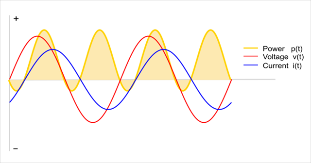
so power actually flows both ways in any non-trival situation, even if by convention we sometimes ignore it.
- Andy.
As I understand it, not just RCDs - other devices (e.g. some MCCBs) can suffer similarly, and presumably some AFDDs (with or without RCD function included) might too? There might be related problems even with simple fuse carriers - e.g. older types that leave one end of the fuse connected to the load circuit as it's being changed (but as a shock hazard rather than equipment damage, but basically the same cause - having a voltage where it wasn't expected).
I've been whittling down from an extensive list of issues that have been discussed here and elsewhere – in terms of the intended effect of this amendment and the potential pitfalls.
I was very sceptical but now I’m absolutely in favour of the substantive effect, and I’ve tried to capture that in a way which conveys some of the rationale.
But below is my current draft. I don't think I'll be adding or removing much more. My proposed Note 4 is an interesting pandora's box - I once encountered an incident where a single phase induction motor in a compressor was backfed from the pressure vessel, I think the starting capacitor allowed the windings to remain excited and it made a right mess of the DOL starter. Fortunatly it didn't make a mess of an operators hand. It should have had a non-return valve but that's another story.
[DRAFT]
Part 5 Chapter 53:
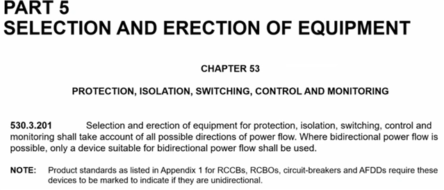
530.3.201 Selection and erection of equipment for protection, isolation, switching, control and monitoring shall take account of the conditions at each set of connection terminals when the installation is in each operating state and under single fault conditions.
Consideration shall be given to:
(i) Sets of connection terminals that may remain live after a protective device has operated.
(ii) The transient behaviour of any generating set when it is disconnected from the rest of the installation.
(iii) The prospective fault current (Ipf) that may flow through the device in the event of a fault at each set of connection terminals.
It is recommended that devices for unidirectional operation are not selected for use where bidirectional power flow is possible.
Note 1: Generating sets might remain live and their terminals may be at an abnormal voltage and/or frequency after they are disconnected.
Note 2: This does not preclude the use of unidirectional devices when it is assessed that the device is suitable for use with a particular generating set, including under single fault conditions, without impairing safety.
Note 3: Product standards as listed in Appendix 1 for RCCBs, RCBOs, circuit-breakers and AFDDs require these devices to be marked if they are unidirectional.
Note 4: Equipment which accumulates energy such as machinery with substantial kinetic energy in the inertia of their moving parts, may under fault conditions unintentionally generate electrical energy.
[/DRAFT]
As I understand it, not just RCDs - other devices (e.g. some MCCBs) can suffer similarly, and presumably some AFDDs (with or without RCD function included) might too? There might be related problems even with simple fuse carriers - e.g. older types that leave one end of the fuse connected to the load circuit as it's being changed (but as a shock hazard rather than equipment damage, but basically the same cause - having a voltage where it wasn't expected).
I've been whittling down from an extensive list of issues that have been discussed here and elsewhere – in terms of the intended effect of this amendment and the potential pitfalls.
I was very sceptical but now I’m absolutely in favour of the substantive effect, and I’ve tried to capture that in a way which conveys some of the rationale.
But below is my current draft. I don't think I'll be adding or removing much more. My proposed Note 4 is an interesting pandora's box - I once encountered an incident where a single phase induction motor in a compressor was backfed from the pressure vessel, I think the starting capacitor allowed the windings to remain excited and it made a right mess of the DOL starter. Fortunatly it didn't make a mess of an operators hand. It should have had a non-return valve but that's another story.
[DRAFT]
Part 5 Chapter 53:
530.3.201 Selection and erection of equipment for protection, isolation, switching, control and monitoring shall take account of the conditions at each set of connection terminals when the installation is in each operating state and under single fault conditions.
Consideration shall be given to:
(i) Sets of connection terminals that may remain live after a protective device has operated.
(ii) The transient behaviour of any generating set when it is disconnected from the rest of the installation.
(iii) The prospective fault current (Ipf) that may flow through the device in the event of a fault at each set of connection terminals.
It is recommended that devices for unidirectional operation are not selected for use where bidirectional power flow is possible.
Note 1: Generating sets might remain live and their terminals may be at an abnormal voltage and/or frequency after they are disconnected.
Note 2: This does not preclude the use of unidirectional devices when it is assessed that the device is suitable for use with a particular generating set, including under single fault conditions, without impairing safety.
Note 3: Product standards as listed in Appendix 1 for RCCBs, RCBOs, circuit-breakers and AFDDs require these devices to be marked if they are unidirectional.
Note 4: Equipment which accumulates energy such as machinery with substantial kinetic energy in the inertia of their moving parts, may under fault conditions unintentionally generate electrical energy.
[/DRAFT]
We're about to take you to the IET registration website. Don't worry though, you'll be sent straight back to the community after completing the registration.
Continue to the IET registration site