
I had an email this morning from the IET telling me that a Draft for Public Consultation has been published for Amendment 3 to BS 7671.
Details here electrical.theiet.org/.../
JP
I had an email this morning from the IET telling me that a Draft for Public Consultation has been published for Amendment 3 to BS 7671.
Details here electrical.theiet.org/.../
JP

I think there's an issue with TT systems if a voltage dependant RCD was providing fault protection.
More generally, a L-PE fault typically causes a reduction in the voltage on L and an increase on PE (a portion of which will be reflected onto N on a TN-C-S system) - so generally it should be expected for the L-N voltage on the supply of any RCD to reduce - as you say often a problem for TT where the RCD element is relied upon for ADS, but also for TN where Zs is too high for the overcurrent devices to open promptly. I had an idea in my head that RCDs were meant to operate down to 50V to allow for such eventualities (below 50V the touch voltage shouldn't be so much of a worry, so lack of disconnection could be tolerated) - but I'm not sure now where I got that idea from..
- Andy.
I had an idea in my head that RCDs were meant to operate down to 50V to allow for such eventualities (below 50V the touch voltage shouldn't be so much of a worry, so lack of disconnection could be tolerated) - but I'm not sure now where I got that idea from..
Most will work at much lower voltages - the application notes for the controllers suggest that many would operate at less than 100V. But in the absence of MIs to the contrary the position in EN 61009-1 is 0.85-1.1x rated voltage.
Many of the tests will include impedances so yes there would be some drop from load current in addition. A fault of negligable impedance would operate the MCB function anyway.
We need to know that touch voltages are < 50V. But that's not the same thing as the RCBO needing to operate down at <50V. And 701.415.2 might allow supplementary bonding to be omitted on RCD protected circuits - but only subject to conditions including that the protective equipotential bonding is okay. If the fault is on the DNO's network then the MET does the job of keeping touch currents <50V anyway, supplementary bonding sould only come into play if there's a fault within the installation - and again the MCB function would handle that.
However if someone has heavily loaded submains with too much Vd then it might go very badly very quickly.

if we really do mean it may not work below 0.85 of 230V == 195 volts RMS then in many parts of Europe the mains at the entry point to the building could be perfectly in spec at 207- 253 and in the UK 216V min. (as we seem to never have adopted the proposed -10% limit.)
Even working well, this leaves very little for in-building drop between entry point and boards at the ends of sub-mains to outbuildings or whatever.
I must admit I have seen, and used a line low of 50V assumption ,and indeed tested and found RCBO units that are quite happy with it (wylex and related if anyone needs a name that works OK)
Equally I have heard of folks who could not get standard RCDs to go on 110V supplies - maybe this is why.
M.
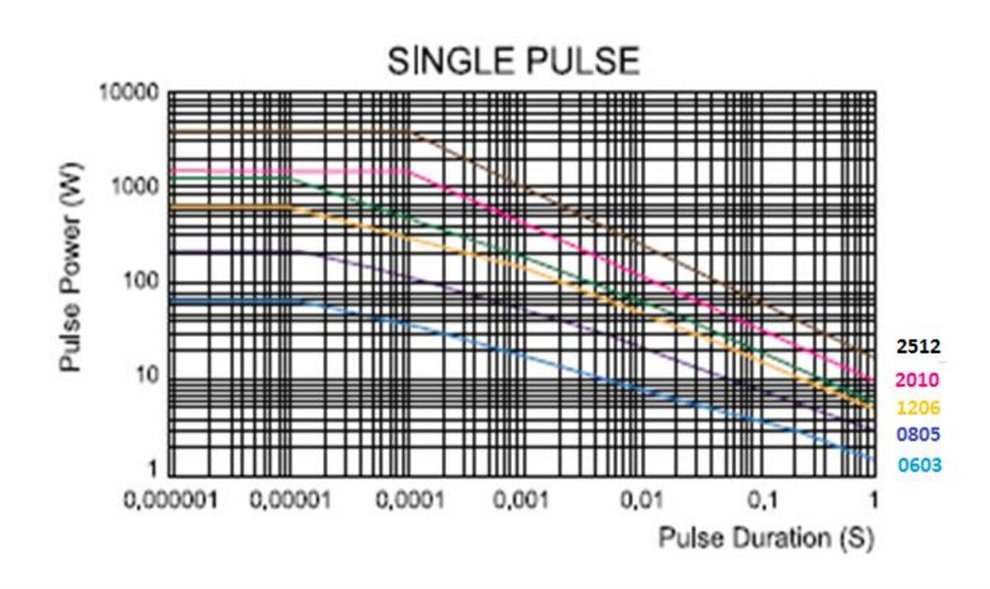
Perhaps this transient rating data from Vishay will re-assure you that it needs to be fast, but so long as it is then all is well - unless the mechanism jams.
Mind you I have heard of ones that did not trip and then went off with a bang. And any motor or capacitive load that provided significant voltage hold up after contact opening might not be that great either.
'continuous' in this context means a succession of repeated (but widely spaced) pulses
![]()
Data from most other makers of SMD resistors are broadly similar - the time constant kink at 100-300ms is set by the ceramic substrate of the resistor and any longer term trend has more to do with the PCB solder pad size and cooling that way. Note that for high resistor values, a flash-over voltage limit may crimp the higher power/short pulse end of the curve.
Oddly TE connectivity publish data for theirs for lone pulses that disagrees and shows no slow kink - this suggests a non repeating pulse can be quite a bit higher in amplitude. This family of lines seems to be near, but not quite, constant energy - so closer to an I2t type rating.
Regards, Mike
edited for unclear grammar.
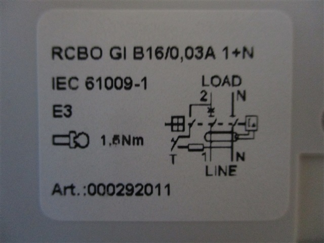
Very interesting point about RCBOs, the test button is held down on a Locked off RCBO, can link Nout to Lin through a 5.4k ohm resistor? calls into question the robustness of current safe isolation practices.
Although many modern RCBOs seem to have a 3rd contact that breaks the test circuit when the device is opened.
e.g.
- Andy.
calls into question the robustness of current safe isolation practices.
Yes it doesn't sit well with me. On the one hand the resulting current flow from this in addition to skin resistance would be unlikely to cause injury on it's own. On the other had if you got a shock of this whilst e.g. on a ladder then it could result in death or serious injury.
Although many modern RCBOs seem to have a 3rd contact that breaks the test circuit when the device is opened.
Yes, i wonder if any of the one's i've dismantled achieve this but it's not apparent because when you dismantle a RCBO then springs fly everywhere. I metered one and it certainly didn't isolate the T button - and IEC 61009-1 appears silent on the question too - I would have expected it to require e.g. the insulation test in open state to be performed with all controlls that aren't capable of locking in the most adverse state.
Perhaps this transient rating data from Vishay will re-assure you that unless the mechanism jams, it needs to be fast, but so long as it is then all is well.
Yes the transisent rating is far higher than the short term overload rating - which is based on 5s. So no doubt if the contacts open then it's not an issue - save for those that are entirely downstream of the contacts in the event of being energised from the load terminals. That said a grid tied inverter would interrupt power within 5s too so that shouldn't be a problem either.
I think it is becoming clear that the issue is DC current depriving the thyristor/triac of the opportunity to switch off - just a shame the BEAMA report didn't say that. I think the overall solution of having Type A's which interrupt downstream of the triac is a pragmatic one as opposed to the more costly option of requiring Type B's. But two obvervations in this respect:
1) Bidirectional RCBO's already exist - some of these might not be compatible with this arrangment because the requirement for an RCBO to be bidirectional is that it can interrupt a fault current to it's Ics rating. I'm not sure that knowing an RCBO can reliably interrupt a 6kA fault fed from an inverter is particularly useful when we know the inverter's short circuit current is <40A.
2) The new Bidirectional RCBO's appear to place the electronics on the "supply" side. This is perfect for the scenario where you've got a grid tied inverter because you know the DNO's supply is AC due to the big 50Hz transformer the DNO uses as opposed to the switching converter that the inverter uses. But it's a misnomer to call them Bidirectional - they are still directional in respect of how they behave in response to a fault with DC components.
Where can this go wrong?
1) An RCBO DB with new Bidirectional RCBO's goes into island mode, RCBO's other than the one for the inverter trip with an enormous bang because they've got their electronics pointing towards the inverter. This is a preventable problem but nobody see's it because we're all taken in by the idea that they're "Bidirecitonal". - Hopefully the RCBO protecting the inverter would trip first but we don't know that because there's no selectivity between two 30mA RCBO's, and in any case the inverter could very reasonably be on an MCB.
2) An RCBO that is Bidirecitional according to BS EN 61009-1, but not according the assumptions made in this ammendment is used. This is less likely because all the prominent manufactuers are pivoting towards this, but the "manufacturers" are often in fact "importers" who don't have a clue what's inside their product and depend upon a test report. So if you go to the far east and ask a manufacturer to make you an RCBO that's bidirectional - and have IECEE test report to that effect - then you'd be quite reasonably placing a bidirectional product on the market and an electrician will quite reasonably depend on that to protect an inverter. Without a national departure in BS EN 61009-1, then once people forget about this ammendment and move onto the next shiny thing accidents are going to happen.
3) RCBO's used on off-grid systems.
What's the solution?
I think the focus should be less on the "bidirectional" issue and more on ensuring that any RCBO used in conjuction with an inverter is declared in the MI's to be suitable for use with inverters subject to the inverter's own MI's declaring compatibility with Type A RCBO's. This avoids getting bogged down in trying to get a national departure in BS EN 61009-1 - because the MI's would be over and above. It also avoid the absurdity that the new "bidirectional" RCBO's may not be compatible with inverters if connected in reverse. This creates a pragmatic middle ground between inexpensive Type A's and Type B's which are largely unnescessary in these applications.
Thus it seems to not meet the requirements for a PEI (e.g. 823 (iv) or 822.1).
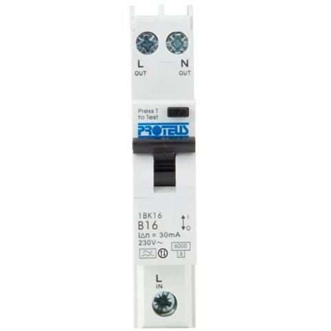
I give you Schrödinger's RCBO. Bidirectional in the MI's, unidirectional according to it's terminal markings.
In fairness I've brought this to attention of Proteus who are changing their terminal markings.
I give you Schrödinger's RCBO. Bidirectional in the MI's, unidirectional according to it's terminal markings
I've a feeling there may be a lot like that - I asked another manufacturer about their single module RCBOs who replied that there wasn't a safety problem with them feeding a PV system, but if I wished to upgrade they're recommend the 2-module version (which didn't have the SUPPLY/LOAD labels). A new version of badge engineering perhaps.
- Andy.
We're about to take you to the IET registration website. Don't worry though, you'll be sent straight back to the community after completing the registration.
Continue to the IET registration site