Construction sites and the use of RLV, guidance on the use of residual protection?

 RCDs on 110v sockets

from the discussion above, which is a few years ago, a conclusion was made that RCD’s are not required for RLV/ CTE transformer used in construction sites from Sec 4. 
It is clear from section 4 that additional protection for RLV sockets is not a requirement, for obvious reasons CTE 55v etc. 

however I have noticed a more recent trend of RCCB’s integral to the secondary side of the windings being implemented to ensure fault protection that can clear within the 5 second disconnection time under 411.8.3. It would seem primarily this is due to chaining multiple extension leads together or excessive lighting circuit lengths, which are difficult to account for except by direct supervision on site. 
Blakley, being one of the leading manufacturers offer a great deal of good technical guidance on the subject - but largely it would appear the practice of having both RLV + residual protection combined into one transformer is down to preference rather than a requirement of BS7671 or BS7375 for that matter, meaning this would be ‘best practice’ as apposed to mandatory unless a contractor were to make part of their policy. 
I would be interested in the forums opinions on this subject, and your own experiences, I think there are changing trends in the industry as to what was historically an acceptable risk may no longer be the case, particularly I’ve noticed 110v Tx plugged into blue commando sockets with a 30mA RCD protecting the primary side, I’m unsure what degree of protection this will offer to outgoing artic flex on the secondary side and it doesn’t seem it would be the same as a multiple pole device that’s installed on the secondary side?

Parents
  • From a practical point of view, there is little need for RCD protection on 110 volt center tapped supplies. Without an RCD, disconnection times in the event of earth faults are likely to exceed those permitted for 230 volt mains circuits.

    But does this matter at the much lower voltage ? On a 230 volt mains circuit, presuming similar sized live cores and CPC conductors, then during an earth fault the case of any class one appliance will be live at 115 volts, less risky than full mains voltage, but still potentially dangerous. Hence the need for RCD protection in order to promptly disconnect such faults.

    On a system with only 55 volts to earth, then the touch voltage on a class one appliance during an earth fault will be only 27.5 volts, which is very unlikely to be dangerous, and prompt disconnection therefore a lower priority.

    It is increasingly common to provide RCD protection on 55/110 volt circuits, and this does no harm, but the actual need is debateable.

    An RCD on the 230 volt input to a site transformer will give NO PROTECTION to the 110 volt output. Anyone who doubts this should try a simple experiment. Plug in the transformer to the RCD 230 volt socket. Connect a test lamp between either pole of the output and the protective earth. Does the input RCD trip ?

    An input RCD is a wise precaution against a damaged  mains lead or plug or transformer but gives no protection to the output.

  • I suppose a 30mA RCD does give some additional protection (e.g. touching a live conductor on a damaged flex without there being a fault to PE to halve the touch voltage) - but at just 55V to earth for a single phase CTE system (or 63.5V for a 3-phase system) the risks aren't huge. While BS 7671 does talk about a 50V touch limit for many circumstances, that does increases to 70V for some outdoor situation (e.g. EVSE) - which probably aren't any better in terms of footware and exposed/extraneous-conductive-parts within reach to that of a building site.

    The last sentence of 411.3.3 seems to be clear that 30mA additional protection isn't required for RLV systems as far as BS 7671 is concerned.

       - Andy.

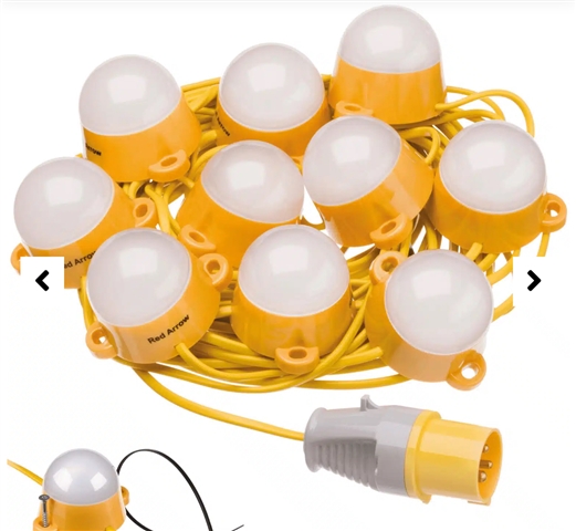
  • Which is what I said when opening, the risk is from the practice of 100’s meters of LED festooned lights or half a dozen extension leads chained together, when a fault occurs at the end of line the result is the cables will melt until bursting into flames due to the supply not disconnecting, which will pose a risk of injury 

Reply
  • Which is what I said when opening, the risk is from the practice of 100’s meters of LED festooned lights or half a dozen extension leads chained together, when a fault occurs at the end of line the result is the cables will melt until bursting into flames due to the supply not disconnecting, which will pose a risk of injury 

Children
  • Which is what I said when opening, the risk is from the practice of 100’s meters of LED festooned lights or half a dozen extension leads chained together, when a fault occurs at the end of line the result is the cables will melt until bursting into flames due to the supply not disconnecting, which will pose a risk of injury

    That's a bit different from addition protection (415 style). If a fault (short) does occur - whether L-PE or L-L - ordinary overcurrent protection should prevent the cables overheating - let alone melting or bursting into flames. It may wall take a lot longer than one might expect for ADS, but as long as there's no shock risk, that's not really a problem. 5s is just a convention to make the calculations easier (longer than that then heat loss starts go dominate and you can't really assume adiabatic conditions, so it all gets a lot more complicated). On the other hand as long as In ≤ Iz, then the protective device (either the fuse wire or the thermal element of an MCB) will heat up a a rate related to the heating of the conductor it's protecting, and it all comes out in the wash. An RCD will do nothing to protect against L-L covercurrent in any event, so as as a fire precaution it's doing half a job at best (especially if double/insulated 2-core flex is involved and any meting wouldn't cause a fault to PE as a side effect).

       - Andy.

  • Exactly P-E, practices such as plugging splitter boxes in 32A outlets and then splitting many 16A leads from it or worse still site electricians swapping lighting MCB,s out for 63A breaker when they cannot stop the manufacturer MCB from tripping when long lengths of LEDs are installed and switched on, this is why the circuits will not trip on earth fault. 
    grouped residual protection on the secondary side means fault protection will be assured- regardless of external influence 

  • grouped residual protection on the secondary side means fault protection will be assured- regardless of external influence 

    Not against L-L faults - which is the only fault you can get on festoon lighting.

       - Andy.

  • Are you sure, I thought they are 3 core, I’ve not seen anything that says there class II 

  • This type are class I

  • Are you sure, I thought they are 3 core

    Traditional festoon lights (in the old days used with insulation piercing lampholders) was certainly two-core - no point in having a c.p.c. since there were no exposed-conductive-parts to connect to.

       - Andy.

  • This type are class I

    Are you sure - the flex looks to be oval rather than round to me - which usually means 2-core.

       - Andy.

  • While the spec sheet says Class I - the installation instructions (www.redarrowelectrical.co.uk/.../connectable-festoon-kit-instructions.pdf) admit it has "1 x 2 core 0.75mm 2 cable" - so go figure!

      - Andy.

  • Doesn’t the spec show a double insulated symbol ? 

  • Yes, I guess the drivers need an earth, I believe they can be wired from scratch on-site. It’s recommended to use 2.5mm arctic flex and limit runs to 50m to account for volt drop