EVSE DC earth leakage limits with slowly increasing current

Hi, I am testing a product that has been certified to meet TUV IEC 62955.

I have tested the DC earth leakage and found that if the earth leakage rate of change is kept over 10uA per second the product will trip correctly (under 6mA).

If the rate of change is less than this the product will not trip until currents of 15mA (or greater) are reached.

Is this product safe to be installed?

Thanks,

Nick
 

  • I have tested the DC earth leakage and found that if the earth leakage rate of change is kept over 10uA per second the product will trip correctly (under 6mA).

    Are you applying this as a residual DC current?

    If the rate of change is less than this the product will not trip

    That is practically steady DC ... which ought to be picked up by the Type A RCD required by BS 7671 to accompany the RDC-DD ?

    Have you checked what BS IEC 62955 says about the test conditions (because that is what the product is certified to)?

  • Interesting find - I suspect it passes  the standard test, because the test method does not consider a fault may sneak up slowly.  (and 10uA/second, suggests ramping  up to the 6mA in an 10 minutes or more )

    However, it does suggest that a level of DC may be not be detected that has the potential to blind upstream RCD protection, if that upstream RCD is particularly vulnerable.

    In practice a fault that comes on that slowly and smoothly is very unlikely (real faults tend to come on with all sorts of current steps discontinuities as things break down) and the risks from using the device will be small.

    But it suggests the DC sensing method has some baseline drift compensation that is struggling, and is in effect the DC fault detection is very slowly AC coupled. I presume this is the result on a sample of one, and it would be interesting to know if that means others from the same design will have faster or slower rates of base-line drift, as if some are much faster then it could result in faults being missed.

    I think the answer to the exam question is 'probably, but not too sure'

    Mike.

  • Yes the product meets all of the test conditions of IEC 62955, however I believe that it is not measuring true DC and instead only able to measure low frequency AC. There might be some sort of zero offset compensation in place to remove low frequency drift. The manufacturer has said that this is a design feature and that as far as they are aware as long as it meets IEC  62955 then it is safe to use.

  • There are other issues that cause it not to trip - I think as long as there is less than 6mA of change within 30 seconds the product will not trip (it doesn't' need to be a gradual ramp). I am worried that this will cause upstream RCD binding and I was hoping that there would be something in the regs that cover this situation. I've not yet carried out a long term test and my fear is that over the course of a couple of hours this current could continue to increase to even higher levels. IEC 62955 does not have any long term or absolute test thresholds (only step changes and ramp from <2A to 6A in <30s

  • I know the very slowly appearing fault is not tested, but part of me does wonder  if it should be.

    Equally 'zeroing' a DC current measurement from clamp on magnetic devices is pretty much essential, as anyone with a DC clamp meter will attest, partly due to the earth's magnetic field and also to slow release of deep level states (late relaxing hysteresis)  in core materials. (whee it was magnetized at some point, and then mostly un-magnetizes very quickly, but a few 'sticky' magnetic domains stay aligned  after the stimulus has gone, and flip state on a scale of  hours or even days later)

    This does mean that some base-line drift is inevitable, and a current that rises slowly compared to that correcting interval (time) will be mistaken for drift and nulled out.

    Flux gate sensors are usually better than hall effect in this regard, as the core is being periodically de-gaussed but they need more circuitry and power and are not as easily miniaturized. I'm not sure what sensor is in these things.

    Given the price of some makers options, one feels it could almost be a squid, but I doubt itSlight smile

    Mike.

  • Tester manufacturers have been tweaking their testers due to testing issues, why are you testing?

    support.myenergi.com/.../4403885493265-zappi-6mA-DC-protection-to-IEC-62955

  • also very interesting - as an electronic equipment design authority, the test is not that ambiguous to me (!)- either the DC appears semi-prompt for one test, or rises by 4mA in 30 seconds from 2mA to 6mA in the other.

    Anything that is a non linear ramp has faster sections than the linear (hardest) case, so the responsible designer should be happy it will trip inside this, say linearly from just over 2mA to just under 6mA also ramping in rather longer than 30 seconds...
    With modern digital test gear smooth ramps may be thought of as hard by the software types , and faked by a staircase on a DAC, but a combination of suitably fine steps and or analogue smoothing of that should be possible. I wonder how they can make something that  fails that and not notice.

    Mike

  • There are other issues that cause it not to trip - I think as long as there is less than 6mA of change within 30 seconds the product will not trip (it doesn't' need to be a gradual ramp). I

    I see what you mean.

    I am worried that this will cause upstream RCD binding and I was hoping that there would be something in the regs that cover this situation.

    BS 7671 has only product standards to refer to in this regard. If there are deficiencies or gaps in product standards, that is a potential issue, but one for product standards to address I think. BS 7671 cannot really get into the intricacies and complexities of performance standards for products.

    There is nothing to stop the manufacturer addressing this though? 'I knew about it but decided not to address' might not go down well ?

    The manufacturer has said that this is a design feature and that as far as they are aware as long as it meets IEC  62955 then it is safe to use.

    Thank you for clarifying what you were looking at.

    Standards might not cover every eventuality for a product's safety and probably do not hold the manufacturer 'harmless' ... for example (and an extreme one at that), there's no check in BS IEC 62955 for the level of ionizing radiation emitted from the product, but we know we ought not to give people radiation burns and the related side effects?

  • This product uses a novel technique (i.e. cheaper) to measure the DC current using an off the shelf current transformer. My testing shows that it can't reliably measure DC. It has been design to pass IEC62955 which it does so as far as the manufacturer is concerned it is safe to use in the UK. I just don't want to see them installed without an actual DC 6mA RCD 

  • This is very interesting, as it surely cannot be just extending the bandwidth down to 10mHz or whatever it needs to see a ramp or triangle that slow as a normal transformer coupling.Do you know what the novelty in the technique is  by any chance ?

    The only way I can imagine is a variation on flux gating, and I'd have thought the extra electronics and the EMI the driving waveform inevitably injects would be prohibitive - given that Hall effect devices are cheap enough to build two into every brushless computer fan.

    That said I see that it is being done by at least one maker.

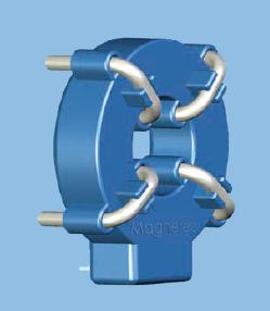
    https://www.magnetec.de/storage/2022/07/mag_Broschuere_Fluxgate-BasedResidualCurrentSensors_web.pdf

    albeit with a more carefully controlled magnetic material and a better fixed winding geometry than  a plain transformer. (though that may also be to aid automated PCB population as well.)

    Mike.

    PS if it is flux gating, its not all that novel as an idea - in the late 1950s oil survey companies were using them to spot local variations in the earths magnetic field on the surface to map out the geology beneath.