CSA on a Radial, what length would you reach with a 4mm?

So I have been down a rabbit hole for some time now and need a bit of clarification.

Possibly someone might be able to explain Fig 15B - Radial final circuit arrangement
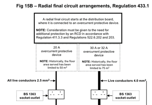
it's suggested that 4.0/1.5mm cable could serve a 75 m2 on a 30A or 32A CB

what would the length be of that cable?

when I perform a voltage drop calculation the length of the cable is 32m which is no where near 75m.

The OSG mentions that the max length for a radial on a 32A CB is 43m with an assumed load of 26A.

Anyone able explain how 75 min fig 15B has been worked out, surely there should be a not stating what length cable its equivalent to.

on a separate note what if the radial circuit was supplying 1 x 13A socket, is there an equation to work out the overload allowance of a circuit or is it simply Ib < In < Iz?

if so then what would the maximum load be expected on a 13A socket? there's nothing stopping someone plugging in an extension lead or adaptor to increase the load.

Parents
  • Thank you all for the feedback, much appreciated, I think this has been worthwhile or at least interesting for me.

    This whole scenario got me thinking about another issue that isn't very clear, if you prefer I could open a new post if not below we expand on this.

    Suppose we are supplying a fixed load to a piece of equipment, for example an electric gate made out of metal, which has a 230V supply to the motor.

    The distance is 40 metres from the board, the cable is SWA buried directly in the ground.
    Do you export the PME or disconnect the PME?

    I'd disconnect the PME and use an earth rod, but leave the SWA connected at one end for protection.

    Now let's say, the gate motors are 24V, I probably wouldn't disconnect the PME because there would be electrical separation through the 24V transformer.


    I would like to know what you would do.

Reply
  • Thank you all for the feedback, much appreciated, I think this has been worthwhile or at least interesting for me.

    This whole scenario got me thinking about another issue that isn't very clear, if you prefer I could open a new post if not below we expand on this.

    Suppose we are supplying a fixed load to a piece of equipment, for example an electric gate made out of metal, which has a 230V supply to the motor.

    The distance is 40 metres from the board, the cable is SWA buried directly in the ground.
    Do you export the PME or disconnect the PME?

    I'd disconnect the PME and use an earth rod, but leave the SWA connected at one end for protection.

    Now let's say, the gate motors are 24V, I probably wouldn't disconnect the PME because there would be electrical separation through the 24V transformer.


    I would like to know what you would do.

Children
  • Now let's say, the gate motors are 24V, I probably wouldn't disconnect the PME because there would be electrical separation through the 24V transformer.

    Whether it's separated from the PME depends on the type of 'transformer' and whether PELV is used. PELV is quite common in Machinery installations (and the Machinery itself being outside the scope of BS 7671, covered by BS 7430).

    Do you export the PME or disconnect the PME?

    I'd disconnect the PME and use an earth rod, but leave the SWA connected at one end for protection.

    {Reg 411.3.1.1} Leaving the SWA connected at one end means more than simply terminating in a stuffing gland. According to BS 7671, you'd need to prevent the CPC from one earthing system being simultaneously accessible with that of another earthing system ... potentially even in maintenance (including inspection and testing).

    Achieving this, whilst permitting testing at a future date to validate ADS, is no mean feat !

    Nothing in legislation, nor BS 7671, prevents the gate mechanism from being connected to PME.

    Worse, if someone in future connects an EV to the PME earthing arrangement of the installation, say using an open-PEN disconnection device (OPDD) , or an outside lamp, with exposed-conductive-parts that are simultaneously accessible with exposed-conductive-parts of the gate, this is also an issue for BS 7671 {again 411.3.1.1}.

    Having said that, it depends what street furniture outside the installation is simultaneously-accessible with the exposed-conductive-parts of the gate {also see 411.3.1.1}.

    Overall ... what is the justification for creating a separate earthing system (in the particular circumstances) ... I'm not sure this can be applied (either way) as a "rule of thumb"?

  • Suppose we are supplying a fixed load to a piece of equipment, for example an electric gate made out of metal, which has a 230V supply to the motor.

    The other consideration is whether the motor unit is Class I or Class II - a lot of equipment intended for outdoors is Class II these days despite metal housing.

       - Andy.

  • That's a good point, maybe the gate example wasn't the best scenario.

    You are right though most things made these day used out side are Class II.

  • You have given me a lot to think about, as you say there is no "rule of thumb"