I am hearing from my network that the DPC for AMD 4 went on line this morning and is available on the BSI website.
JP fires starting gun for a very long thread?
JP
I am hearing from my network that the DPC for AMD 4 went on line this morning and is available on the BSI website.
JP fires starting gun for a very long thread?
JP
PNB - the new diagrams (3.9b (i) & (ii)) seem confused to me (or at least I'm confused by them). The seem to show the (source) electrode & N-PE link as being part of the consumer's installation - which doesn't seem credible for supplies taken from the grid at LV - on all the PNB systems I've seen the electrode and N-PE link are part of the supplier's equipment (if on consumer's premises), not the consumers installation (and if they were on the consumer's side there would likely be a breach of the ESQCR 8(4) ("A consumer shall not combine the neutral and protective functions in a single conductor in his consumer’s installation."). For the case of a private transformer, yes the link and electrode would be part of the consumer's installation, but then so would the transformer so the whole diagram should be within the dotted box - and in any case that's likely to be simple TN-S.
- Andy.
I see things more like this:
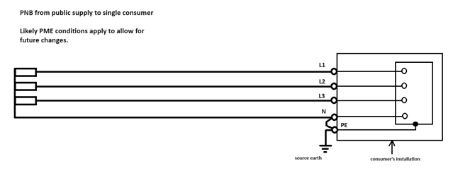
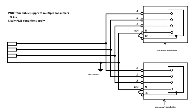
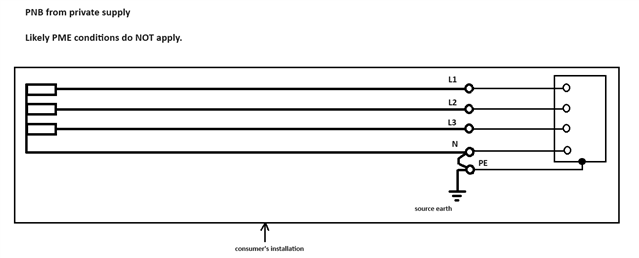
- Andy.
Actually, at least on site where more than one LV TX is in parallel you may see multiple NE links, and it tends to be inside with the TX outside, and then arguably it is part of the consumer side stuff, just upstream of any loads - and I do mean the UK. Note also that the domains of the ECSQR and BS7671 don't overlap - i.e. there are areas of the planet that use BS7671 (Qatar, Malta, probably others ? ) that have no such NE combination prohibition.
But the diagram thing is interesting. I agree that PNB especially is not always clear to folk, even if I think its clear to me.
Perhaps on a related note we should ask DNOs to write in Sharpie on the meter boards what they think the earth arrangement is supposed to be - as they used to have to do when PME first came out
. 
I'm not sure if the standard drawings are inherited from another standard.
Mike.
As per your diagram, isn't the N conductor actually a PEN conductor? My understanding is that the conductor is only N when the LV neutral and LV earth have been separated.
Also, I noticed the PNB diagrams in BS 7671 Amendment 4 don't show a connection between the neutral of the transformer and the PEN. Is this correct?
As per your diagram, isn't the N conductor actually a PEN conductor? My understanding is that the conductor is only N when the LV neutral and LV earth have been separated.
Well spotted, but actually deliberate. My suggestion is that it provides no earthing function upstream of the earthing point since there are no exposed-conductive-parts upstream to connect it to (the transformer metalwork is conventionally connected to the HV earthing system where PNB is used, not the LV one and in the DNO world it's (AFAIK) always in rural areas with overhead lines (ABCs or open wire)- so not even any outers of concentric cables to worry about. So other than the 2nd case it's really TN-S rather than TN-C-S we're dealing with (but the DNOs will likely impose PME conditions anyway, to leave room for future reconfiguration)..
Also, I noticed the PNB diagrams in BS 7671 Amendment 4 don't show a connection between the neutral of the transformer and the PEN. Is this correct?
I thought not - hence they're connected on mine!
- Andy.
Well spotted, but actually deliberate. My suggestion is that it provides no earthing function upstream of the earthing point since there are no exposed-conductive-parts upstream to connect it to (the transformer metalwork is conventionally connected to the HV earthing system where PNB is used, not the LV one and in the DNO world it's (AFAIK) always in rural areas with overhead lines (ABCs or open wire)- so not even any outers of concentric cables to worry about. So other than the 2nd case it's really TN-S rather than TN-C-S we're dealing with (but the DNOs will likely impose PME conditions anyway, to leave room for future reconfiguration)..
Would the single point bonded AWAs not be considered an exposed-conductive part? These are upstream of the LV neutral and LV earth link.
EDIT: my understanding is that the neutral conductor, as per your drawing, will form part of the earth fault loop of most earths faults that can take place within the consumers' installation. Meaning the conductor is acting as a neutral and earthing conductor... i.e. a PEN conductor... Apologies if I'm barking up the wrong tree!
I thought not - hence they're connected on mine!
I agree, I think they need to be shown as connected. Happy to be proven wrong, though.
i.e. yo mean is this a mistake ?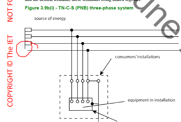
Agree also. Should look more like this (though I have fudged this by care fully cropping the TN-S one. So ignore the dot.. )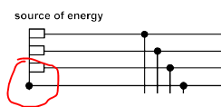
Note that this simplification is OK for a genset, a real transformer will have some kind of HV earth connected to the metal of the core and the tank somehow to operate an HV trip if the primary insulation fails.
M.
Would the single point bonded AWAs not be considered an exposed-conductive part? These are upstream of the LV neutral and LV earth link.
Ah, for private transformers - yes that might be a possibility. I was thinking more of the usual DNO layout which tends not do that sort of thing. Maybe that's even more reason to treat the private/public situations distinctly.
EDIT: my understanding is that the neutral conductor, as per your drawing, will form part of the earth fault loop of most earths faults that can take place within the consumers' installation? Meaning the conductor is acting as a neutral and earthing conductor... i.e. a PEN conductor? Apologies if I'm barking up the wrong tree!
No apologies needed - it's good to debate these things. My counter argument is that it would be the same for the (short) connection between the N-PE link and the star point on a conventional TN-S system - but we don't tend to refer to those as PEN conductors nor say it's really a TN-C-S system. Indeed some care is needed - since it's unlawful in the UK for a consumer to have a combined earth & neutral conductor within their installation, we don't want a situation any attempt to create a local TN system will fall foul of the law.
- Andy.
Would the single point bonded AWAs not be considered an exposed-conductive part? These are upstream of the LV neutral and LV earth link.
Thinking again... wouldn't these be connected to the earth bar, at or downstream of the electrode connection, rather than to the "N"/"PEN" conductor upstream?
- Andy.
We're about to take you to the IET registration website. Don't worry though, you'll be sent straight back to the community after completing the registration.
Continue to the IET registration site