Checking if 1.0mm cpc on 2.5mm cable is acceptable for EICR and where the limit is

Just want to check my calculations and conclusions are correct.
(been meaning to do this for a while)

Checking if a 2.5/1.0mm cpc is acceptable on a 32A  ring final for an EICR.

In this example looking at data for MK 32 A MCB MK data sheet

In the graphs I am assuming the horizontal is PSCC/PFC. In my example I have a PFC of 700A, therefore I2T = about 5000 A/sec

Energy withstand for 1.0cpc  K2S2 = 115*115 * 1.0 = 13,225

I2t needs to be less than K2S2

5000 < 13,225  therefore I am ok.

If I look at the graph and find I2t of 13,000 it looks like I am ok for pscc/pfc  up to about 3K, bit difficult to read with linear graduation on a log scale.

In reality the B type actually switches in 10msec with 5 * rated current rather than the 100msec typically used in calculations.
Parents
  • yes, again the 1mm2 will be fine. As you note most breakers are open, or at least well on the way to open, in a tenth of the assumed period, and even while opening,  the voltage drop across the stretching arc is eating into the power available to drive the full PSSC which is therefore falling..

    Note that breaker makers sometimes publish a let-through figure I2t specific to the MCBs or whatever, or there is an upper bound in the standards.
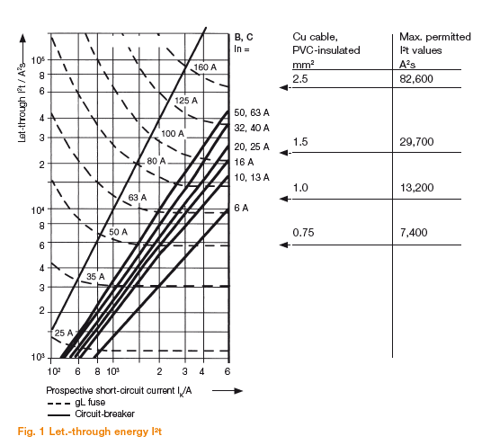
    ABB publish this helpful aide memoire

    from here  The curves are far more revealing than the single figures often quoted, and explain some of the physics.

    1) The dotted fuse curves show that at high fault currents, fuses become more or less constant energy devices - the number of joules to melt and the vaporize a fixed length of fusewire is more or less constant so long as you do it fast enough that no energy escapes out the side....

    2) The solid slopes for breakers however show how at high currents they behave almost like constant speed devices - if you double the PSSC you almost quadruple the damage energy. Perhaps unsurprisingly in a device with moving parts where beyond a certain point, it can't go any faster.
    It is worth realizing that in many ways cables are better protected against really big faults by fuses.

    (and yes, 1mm2 cable really will be protected by a  60A  gL or similar fuse  so long as you have available  PSSC of 6000A plus, but not in a higher resistance setting.. )
    Mike

  • Thanks Mike. I actually find this more interesting than doing the day job, unfortunately sitting doing calculations doesn't generate revenue.

    I remember one of my instructors telling the group that if we ever find 2.5/1.0 it should be an automatic rewire, but in reality for at least 80% of cases it's perfectly fine and for the other 20% unlikely to actually cause a problem.

  • the biggest problem is that the 1mm cores tend to sneak round the sides of the screws and fall out of certain designs of terminal.

    telling the group that if we ever find 2.5/1.0 it should be an automatic rewire


    Note that the common advice in such a case to refer to  tables ZA1 and ZA2 of IEC 60898 or BS EN 6089 - assuming you have these to hand, and if not then look at page 14 of the BEAMA guide here will grossly over estimate the let-through energy in any systems that are not bumping right on the upper limit of PSSC. (compare the effect of a small drop in PSSC by looking at the shape of the ABB curves above.)
    This makes things appear far more dangerous than they really are, and probably leads to a lot of perfectly serviceable / adequate kit being scrapped prematurely.

    Mike

  • fuses.

    (and yes, 1mm2 cable really will be protected by a  60A  gL or similar fuse  so long as you have available  PSSC of 6000A plus, but not in a higher resistance setting.. )

    If I read the graph correctly, the 1mm2 is protected by a 63A gl fuse right down to  just below 1.5KA.

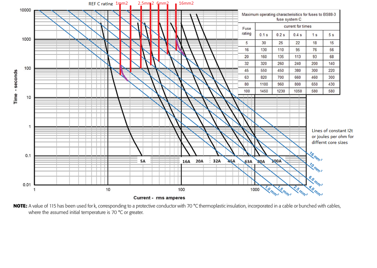
  • True - though I'd not like to get too close to the dotted line.  To see if a cable is really protected or not you need to overlay the fuse curves with the I2t damage level for the cable at the high current end, and the steady state rating at the other.
    Rather like this graph

    edit sorry, this graph where we compare fuse curves, with the adiabatic I2t and steady state ratings of a cable, in this example for refernce  mounting method 'C'. This is not to be used for real designs, think of it more as a teaching aid.

    Note also that a 60A gL fuse is a lot faster than a BS88-3 one - here anything more than a 5A fuse struggles to cover 1mm2.

    Mike

  • If I read the graph correctly, the 1mm2 is protected by a 63A gl fuse right down to  just below 1.5KA.

    For some fuses ... perhaps if you want to make assumptions about the protective device for operating times < 0.1 s ... how valid are those assumptions? Just because the graph stops, doesn't mean the physics stops too !

    The assumption is certainly not always true for circuit-breakers.

  • yes, again the 1mm2 will be fine.

    Not for circuit-breakers in ALL cases of prospective fault current. In this case, it may be OK because of the low prospective fault current, but the the calculation presented does NOT conform to BS 7671 which requires the let-through energy quoted by the manufacturer (or the product standard) to be used for circuit-breakers with operating time < 0.1 s.

Reply
  • yes, again the 1mm2 will be fine.

    Not for circuit-breakers in ALL cases of prospective fault current. In this case, it may be OK because of the low prospective fault current, but the the calculation presented does NOT conform to BS 7671 which requires the let-through energy quoted by the manufacturer (or the product standard) to be used for circuit-breakers with operating time < 0.1 s.

Children
No Data