Checking if 1.0mm cpc on 2.5mm cable is acceptable for EICR and where the limit is

Just want to check my calculations and conclusions are correct.
(been meaning to do this for a while)

Checking if a 2.5/1.0mm cpc is acceptable on a 32A  ring final for an EICR.

In this example looking at data for MK 32 A MCB MK data sheet

In the graphs I am assuming the horizontal is PSCC/PFC. In my example I have a PFC of 700A, therefore I2T = about 5000 A/sec

Energy withstand for 1.0cpc  K2S2 = 115*115 * 1.0 = 13,225

I2t needs to be less than K2S2

5000 < 13,225  therefore I am ok.

If I look at the graph and find I2t of 13,000 it looks like I am ok for pscc/pfc  up to about 3K, bit difficult to read with linear graduation on a log scale.

In reality the B type actually switches in 10msec with 5 * rated current rather than the 100msec typically used in calculations.

Parents
  • If I look at the graph and find I2t of 13,000 it looks like I am ok for pscc/pfc  up to about 3K, bit difficult to read with linear graduation on a log scale.

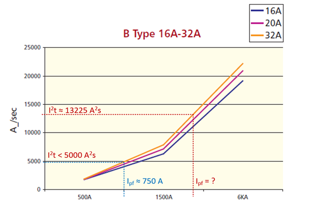
    I think that's the correct approach, BUT the graph can't be ascertained to be in either a linear or log scale for Ipf above 1500 A, so it's not really possible to take a reading of the actual prospective fault current the 1.0 sq mm will be OK for with this device (red dotted lines in the below clip from the data sheet).

    All we could ascertain from the portion of the graph for fault currents > 1500 A, is that 1.0 sq mm will be OK with Ipf of 1500 A or less, but not 6 kA.

    In the graphs I am assuming the horizontal is PSCC/PFC. In my example I have a PFC of 700A, therefore I2T = about 5000 A/sec

    YES, this is the one we can rely on, because the graph is linear up to 1500 A, it is possible to see that the I2t value for a PFC of just under 750 A is a little under 5000 A2s (blue dotted lines in the below), proving the 1.0 sq mm would be OK for this particular installation with the pfc you have ... so, as long as the 700 A is the PFC at the origin of the circuit.

Reply
  • If I look at the graph and find I2t of 13,000 it looks like I am ok for pscc/pfc  up to about 3K, bit difficult to read with linear graduation on a log scale.

    I think that's the correct approach, BUT the graph can't be ascertained to be in either a linear or log scale for Ipf above 1500 A, so it's not really possible to take a reading of the actual prospective fault current the 1.0 sq mm will be OK for with this device (red dotted lines in the below clip from the data sheet).

    All we could ascertain from the portion of the graph for fault currents > 1500 A, is that 1.0 sq mm will be OK with Ipf of 1500 A or less, but not 6 kA.

    In the graphs I am assuming the horizontal is PSCC/PFC. In my example I have a PFC of 700A, therefore I2T = about 5000 A/sec

    YES, this is the one we can rely on, because the graph is linear up to 1500 A, it is possible to see that the I2t value for a PFC of just under 750 A is a little under 5000 A2s (blue dotted lines in the below), proving the 1.0 sq mm would be OK for this particular installation with the pfc you have ... so, as long as the 700 A is the PFC at the origin of the circuit.

Children
No Data