LED ghosting - LEDs remain dimly lit when lighting circuit switch is OFF

I have just had my house rewired. Unfortunately a couple of lighting circuits exhibit LED ghosting - LEDs remain dimly lit when lighting circuit switch is OFF. I am considering adding a capacitor and resistor to form an RC circuit across the switch which hopefully will allow these small currents to dissipate. Does anyone have any other suggestions? What values of resistor and capacitor should I consider?

Parents
  • This is almost certainly caused by capacitive leakage currents between an "always live" wire to the switch and the switched live from the switch to the lamps. With incandescent lamps, these minute currents have no effect, but LED lamps can glow dimly.

    To prevent this, connect a small capacitor across the lamps.  No need for a resistor, and the value of the capacitor is not important. It must however be suited for continued connection to mains voltage. Any small MAINS RATED capacitor intended for interference suppression or power factor correction should work.

    Leave notes explaining what has been done, inside the light switch and the consumer unit, in order to avoid later confusion.

  • try 0.1uF (== 100nF) series 100 ohms, for all but the longest wiring runs this is enough. and  small enough not to cause other issues with power factor or extra current. The R or C can be safely doubled or halved in value without doing anything bad but those values have the advantage they are also available as a ready made mains rated part for contact suppression on small motors.

    example here https://cpc.farnell.com/ampohm-wound-products/fe-sp-hdr23-100-100/contact-suppressor-0-1uf-100r/dp/FT00715?

    or the very similar parts from many other sources. Just watch the voltage rating.

    the resistor saves the switch contacts from capacitor inrush, and the capacitor does voltage division against the capacitance of the wiring (say 50-100pF per metre in the wiring so ten metres of cable is at most 1000pF == 1 nF and voltage division is at least 100:1 - enough to turn most LEDs from 'flicker a bit ' to 'really off')


    Mike

  • Where exactly should these be connected?

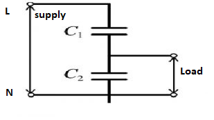
  • In parallel with the load whose voltage you wish to fall to zero when the switch is off. In this case accross the LEDs.
    you are forming a "lossless" AC voltage divider.

    as per the circuit model below.

    Where the 'top' capacitor C1 represents the stray current effect  displacement current through the insulation between the cores of the switch wire when not connected, and the lower one is the thing you are adding to reduce the voltage reaching the LEDs in the off state.
    Mike

    PS if your grasp of the capacitor theory is a bit shakey, capacitors don't strictly conduct current at AC, not like a metal where charge loafs its way along indefinitely.(*) Rather charges pile up  on one conductor rather like folk may gather on a river bank, and pull rude faces and so on to make the folk on the other bank== charges on the other conductor move away , as they are repelled.  However, as far as the wire on the other side is concerned, it is still like a current flowing , just not the same charges come out as went in on the other side - and once charged (all the free charges moved) then current would trickle to a  stop - except with AC it all repeats for ever and current flows in one side and out the other and then reverses.

    *Of course even in a wire, the electrons that drop out of one end are not usually the same ones you put in at the other, just an equal number carrying the same charge, but in principle if you waited long enough with DC flowing they would. Not in a cap.

Reply
  • In parallel with the load whose voltage you wish to fall to zero when the switch is off. In this case accross the LEDs.
    you are forming a "lossless" AC voltage divider.

    as per the circuit model below.

    Where the 'top' capacitor C1 represents the stray current effect  displacement current through the insulation between the cores of the switch wire when not connected, and the lower one is the thing you are adding to reduce the voltage reaching the LEDs in the off state.
    Mike

    PS if your grasp of the capacitor theory is a bit shakey, capacitors don't strictly conduct current at AC, not like a metal where charge loafs its way along indefinitely.(*) Rather charges pile up  on one conductor rather like folk may gather on a river bank, and pull rude faces and so on to make the folk on the other bank== charges on the other conductor move away , as they are repelled.  However, as far as the wire on the other side is concerned, it is still like a current flowing , just not the same charges come out as went in on the other side - and once charged (all the free charges moved) then current would trickle to a  stop - except with AC it all repeats for ever and current flows in one side and out the other and then reverses.

    *Of course even in a wire, the electrons that drop out of one end are not usually the same ones you put in at the other, just an equal number carrying the same charge, but in principle if you waited long enough with DC flowing they would. Not in a cap.

Children