110V 16A sockets in a ring arrangement

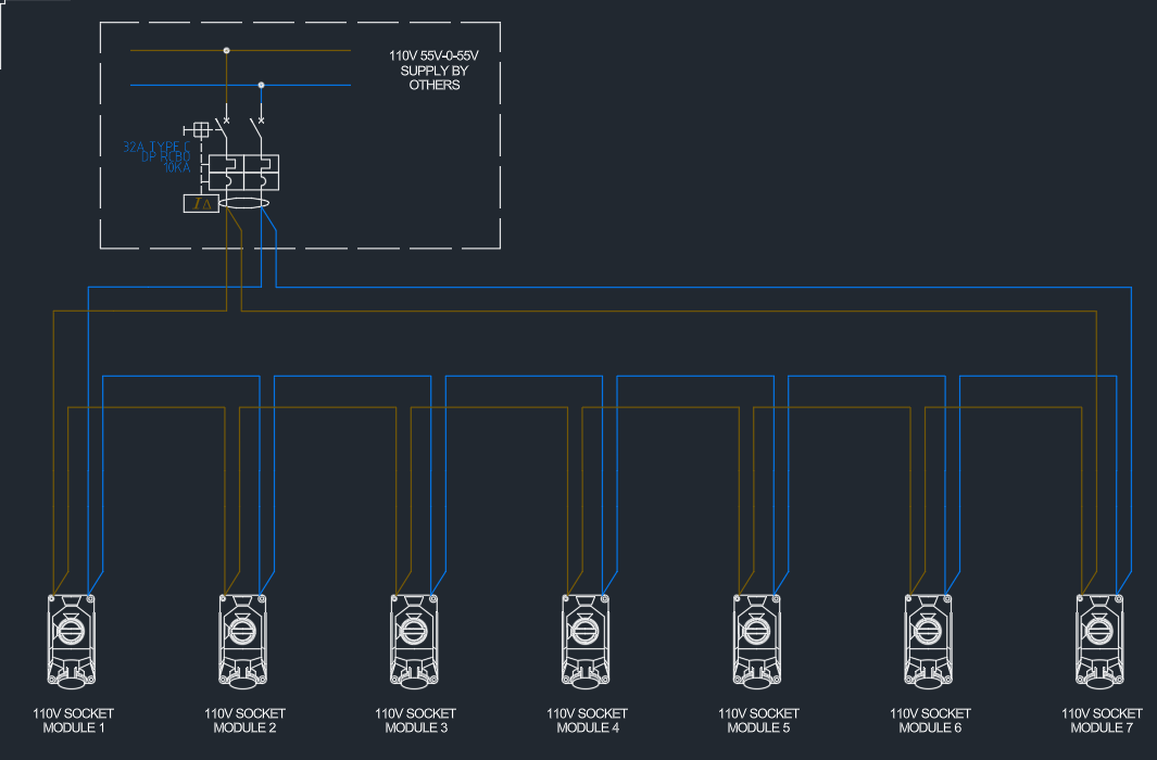
I am planning to make a 110v circuit containing up to 10 x 16A 110V single sockets. The circuit is up to 100m long. Is 32A MCB type C and H07 4mm2 will be ok for it or I need to take into consideration of using RCBO instead and calculate voltage drop to size required cable properly?

Parents
  • sockets 16A (internally fused I guess).

    Are we talking about sockets with interval overcurrent protection - something like this: https://www.cef.co.uk/catalogue/products/1150765-16a-2p-e-110v-unswitched-socket-with-25a-rcd-ip44 (but with an MCB or RCBO instead of an RCCB).

    The furthest socket is about 50m away from Transformer.

    for voltage drop - 4mm² has a v.d. of around 11mV/A/m so 16A (for one leg of the ring) over 50m would give a v.d. of 8.8V - whereas 5% of 110V is 5.5V - so that looks like a problem even before you consider v.d. in the 230V circuit supplying the transformer.

    I suppose that you might be able to arrange the transformer (e.g. via taps) to boost the secondary voltage somewhat, undoing the voltage drop on the 230V side and perhaps increasing the starting voltage on the 110V side, but that wouldn't undo the power losses, so maybe not an ideal solution.

       - Andy.

Reply
  • sockets 16A (internally fused I guess).

    Are we talking about sockets with interval overcurrent protection - something like this: https://www.cef.co.uk/catalogue/products/1150765-16a-2p-e-110v-unswitched-socket-with-25a-rcd-ip44 (but with an MCB or RCBO instead of an RCCB).

    The furthest socket is about 50m away from Transformer.

    for voltage drop - 4mm² has a v.d. of around 11mV/A/m so 16A (for one leg of the ring) over 50m would give a v.d. of 8.8V - whereas 5% of 110V is 5.5V - so that looks like a problem even before you consider v.d. in the 230V circuit supplying the transformer.

    I suppose that you might be able to arrange the transformer (e.g. via taps) to boost the secondary voltage somewhat, undoing the voltage drop on the 230V side and perhaps increasing the starting voltage on the 110V side, but that wouldn't undo the power losses, so maybe not an ideal solution.

       - Andy.

Children
  • I don't understand that bit about voltage drop. Ok, on one leg of the ring which is 50m there is 8.8V drop but this is a ring arrangement so this will be compensate with additional 50m 4mm2 cable to the furthest socket so we should ended up with about half of this amount so 4.4V sounds better now. Current me if I am wrong.

    I have also found VD formula like this but have no idea if this is correct and where is that 4 comes from

  •  if you cannot work out which formula applies and try and memorize them but just get it all wrong, its a recipe for disaster, so lets  chuck all that and  go back to first principles.

    so in big loose handfuls, 1m length of 1mm2 is 16 milliohms cold, and more like 18 when hot.

    but you have 8 such 1mm strands, in parallel, (2 paths of 4mm) going 50m there and then 50m back.So that is ~ 2 to 2.2 milliohms per m, and 100m there and back call it 0.2 to 0.22 ohms, for the round trip  at 16A that is 3,2V to 4V and at 32A that is 6,4V to 8V.

    So, is the max load at the far point 16A or 32A ? that depends how the sockets are laid out.

    Now OK. what is the regulation of the transformer ? don't know but could be up to  5% drop at full load, Then there is the drop in the primary circuit, where of course the voltage is more or less doubled, but the current is halved and you have not mentioned that at all.

    you could be approaching or even exceeding 10%. and then you are getting to a place where a C type breaker will not prompt trip.

    Mike.

  • I don't understand that bit about voltage drop. Ok, on one leg of the ring which is 50m there is 8.8V drop but this is a ring arrangement so this will be compensate with additional 50m 4mm2 cable to the furthest socket so we should ended up with about half of this amount so 4.4V sounds better now. Current me if I am wrong.

    Sorry, I did a bit of simplifications (or sleight of hand) there - which I would probably done better to explain. I presumed there was 50m of cable to the furthest point (so ring had 100m of cable overall) and presumed the ring was balanced and the total load could be up to 32A, with the possibility that all the load could be close to the furthest point. In those circumstances both legs would be carrying 16A each over the 50m - hence the calculation above. You could equally use the /4 formula, but then you'd have to plug in the whole 32A and 100m rather than 50 - so you'd end up with the same figure.

       - Andy.

  • This is the biggest concern I have because the customer is not sharing any data regarding transformer neither protection fuse. It's only guess from previous project made by my colleagues. I am not ever sure if they have RCBO/RCD fitted or just MCB. Basically, I was told to provide 1x 16A socket in each module. There are 8 modules so 8 sockets are required. They are need to be done in ring arrangement and they finish the installation once the unit on site. I am a little bit lost now. Should I increase the cable size from 4mm2 to 6mm2 to decrease VD or split this CCT to 2 smaller ones? I am also waiting for the customer to sent me more details about what is provided on their side so this may clear the situation out a little bit.

  • well, as I kind of said above,  then you are not designing it, they are, and they are adopting all attendant responsibility, and that needs to be made clear to them. You can only design with full data. ;-)

    Do you have a web link to the sockets with build in fuses/breakers that are to be used ? I'd be interested.

    Mike.

  • I was told to provide 1x 16A socket in each module.

    Where did the idea of a ring come from?  Normally they're only used for 13A sockets (because the plugs are fused) or much much larger thing in the distribution world (true ring mains) otherwise radials are much more usual.

    +1 for needing proper requirements if you're going to design it (you'll need Zs for starters even to decide if an MCB will be suitable.  I suppose you could try a "robust" design that could cope with just about any input and load (rather like some people have to do for mobile units) - e.g. a Class-II DB with MCB+RCD for each outgoing circuit arranged as say 8 radials in 10mm² (to get v.d. below 6.875mVA/m for 16A over 50m and stay below 5% of 110V) - but that's likely not to be economic and still potentially be vulnerable to some edge case issues.

       - Andy.