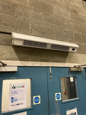
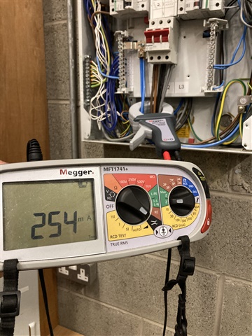
Turning this new heater on jumped the leakage current from 1.8mA to what’s on the screen.


Well, only when the clamp was left as shown. Once raised to a level position, the display dropped to 7mA.
Turning this new heater on jumped the leakage current from 1.8mA to what’s on the screen.


Well, only when the clamp was left as shown. Once raised to a level position, the display dropped to 7mA.
Hmm!!
How well do the jaws on your clamp close when hanging off a cable like that ?
- I suspect that both 1/4A and 7mA are inaccurate and are more of a representation of neither the live nor neutral currents being centrally positioned (nor equally off centre) in the core, and the cancellation of the magnetic fields getting a few percent out of kilter - perhaps more of the flux from the neutral escaping through the gap in the jaws, or is the steel getting magnetically non uniform and needs de-gaussing.
How much current is the heater taking - i.e, what % imperfection in the cancellation are we talking about ?
Mike.
It is a brand new toy connected to a relatively recent 1741A Megger MFT. Jaws fully closed. Tests conducted numerous times. The DB is in the workshop of our training centre so I was just playing. The DB has a very low overall value of insulation resistance to earth (reason unknown) so I was trying to relate the leakage current to that. I would be miffed if the clamp was unable to measure leakage with some degree of reasonable accuracy! Heater draws 25A single-phase.
OK so the 250mA reading is more or less a 1% error in LN cancellation - which is not that great. If you have the time to investigate then experimenting with how much the reading moves with the location of the L and N currents inside the circular core. Also possible the box (steel I presume) is not helping and will distort the fields a bit.
Of course the simple theory says that all the magnetic field is in perfect circles in the core and none in the air in the hole up the middle (curl B being u0J and all that) but we know that in practice the core is not infinite permeability and that the field pattern is imperfect. But with sensible soft iron cores with permability (mu factors) of several thousand it is normally pretty good.Certainly I have clamp meters that do better than that shows - down to better than one part in 1000 (seeing tens of mA with 30A plus flowing ) The 7mA I could believe, the 250mA not really/.
Heater draws 25A single-phase.
So what is the reading with the clamp just around N and the relevant phase (with nothing drawing a current on the other two phases)?
OK so the 250mA reading is more or less a 1% error in LN cancellation - which is not that great.
With there being, in this example, a definite non-zero distance between conductors, the elliptical presentation of the area within the clamp to the conductors will certainly affect whether field cancellation occurs as it ought to in the 'ideal case'. That can be the case even if the neutral current is almost zero (balanced phases)
The clamp should be perpendicular in both its radial axes to the conductors, particularly if the conductors occupy a large area within the clamp as in this case.
We're about to take you to the IET registration website. Don't worry though, you'll be sent straight back to the community after completing the registration.
Continue to the IET registration site