
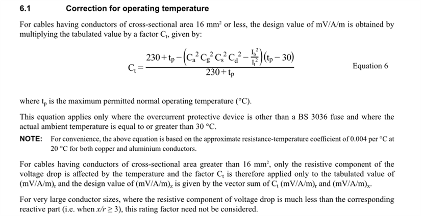
Is the correction factor for thermal insulation deliberately omitted? Page 429 BS7671
Is the correction factor for thermal insulation deliberately omitted? Page 429 BS7671
Actually, having stuck it on a spread sheet, I think it is because Ci is generally punitive (low values). With low values of correction factors there would be no advantage in using the value of Ct derived from the formula to re-assess voltage drop. The real advantage is when there are no correction factors and there is a significant difference between Ib and It.
It's not clear to me why the resistance of copper at temp tp which is what we are considering is affected by any of those factors, all they do is reduce the current rating, as the max permitted temp tp is reached at a lower current! It's not the clearest of ways of looking at it. Regs-speak strikes again
Mike
That said, they clearly don't want you to think about temperature and resistance as Logical intermediate steps in the calculation, but that rather obscures what is going on.
Interesting question ... I'll have to have a ponder. (Although my initial suspicion is that the formula might pre-date the introduction of Ci. As for why the correction factors are in there at all, maybe it's down to comparing Ib with It - the correction factors having being originally applied to Ib before selecting It and somehow having to undo that)
- Andy.
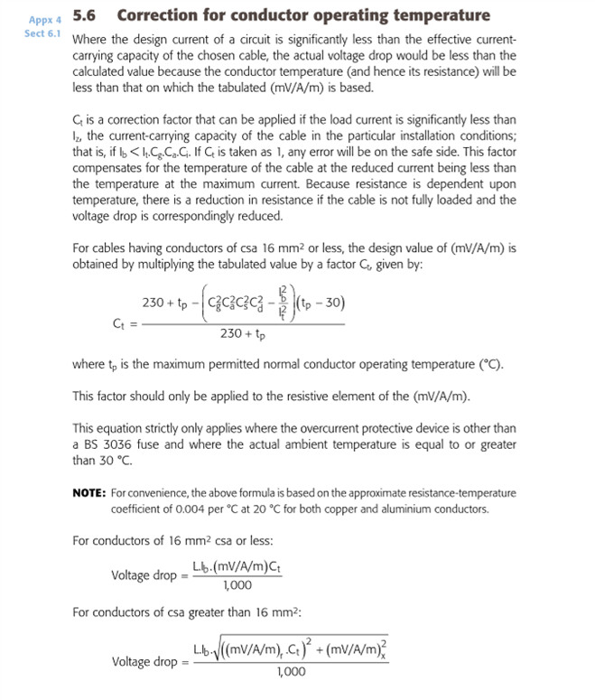
No, quite simply, Ct is applied to It, before It is put into the other formulas, and only applies where the design current is significantly less than the effective current-carrying-capacity chosen. This is explained in Section 5.6 of the IET Electrical Installation Design Guide.
I take it you mean Ci is applied to It before being put in the formula for calculating Ct? In any event, to operate the formula in 6.1 of Appendix 4 of 7671 one must establish the value of It by using either one of the conventional two methods. To do that all correction factors including Ci, Cg, Ca etc are employed. That being the case, why is Cg, Ca etc used to calculate Ct and Ci is not?
From Design Guide;
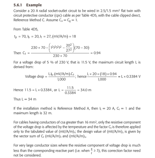
Say in the example above, Cg was 0.78 and no other correction factors applied, Ct would approximate to 0.99, and not worth employing. On the other hand, if Ci was 0.78 and no other correction factors applied, the outcome is 0.94, the same as for the example given above.
why is Cg, Ca etc used to calculate Ct and Ci is not?
I’ve never really given that any thought. I just follow the design sequence starting with determining the final circuit overcurrent protection devices and cables, incorporating the thermal insulation factor (Ci). Once the tabulated current-carrying capacity of the cable (It) is identified in Appendix 4 of BS 7671, the next step is to perform voltage drop calculations. The design guide I use, the calculations for the correction factor (Ct) consider only the ambient temperature and grouping factors. Same as the Ct formula you have shown but without Cs and Cd factors.

sir,
ct is used in volt drop calcs and not used current carrying capacity calcs
ct is more impacted by the temperature of the copper over the full lenght of (r1 + r n)
ct is only slightly changed by the warm copper in the stud walll for a length of only 250mm
i thinks the volt drop is less impacted by the short sections and more impacted by the longer (full length) sections
the full length is in the ambiant environment that impacts the total concudtor length
.5 metre on at 50 metre circuit is 1% of the percentage difference the warm section specifeied as <500mm
ct is not for ccc, it is for vd only.
hope that makes sense i spent a few days pondering it so i am interested on other takes. investedly yours, john walthamstow 17march 2025
I take it you mean Ci is applied to It before being put in the formula for calculating Ct?
Sorry ... took a while to get back to this thread.
I meant Ci is applied to get It ... we then select It so that it is operating at the required conductor temperature (usually 70 deg C).
Once we are at the relevant ambient temperature, we read the value of mV/A/m for the actual cable (usually at 70 deg C at an ambient temperature of 30 deg C).
But, if the cable is operating well below its capacity, it won't be at 70 deg C for an ambient temperature of 30 deg C, so some account can be made of this. Ci doesn't come into it, as it's already been used to derive a minimum value of S for the given conditions, from which the volt-drop is read.

Hi John. I wasn’t suggesting that Ct affects the cable’s current-carrying capacity. I simply work that out first and then calculate the voltage drop.
We're about to take you to the IET registration website. Don't worry though, you'll be sent straight back to the community after completing the registration.
Continue to the IET registration site


