Increasing csa through warm section of an installation

Consumer unit & gas ch combi to be installed in a brick cupboard (1200 x 1200 x 2500, with concrete ceiling ) just off the kitchen. The only cable route out is up over the door and through the brick wall to the main house. I've decided on perforated tray 225mm wide for good spacing which will be mounted 10mm from the wall. I'm comfortable with the cable selection for the 6 circuits on the tray and believe I can negate the grouping factor as per note 2 for table 4C1.

For example;  the kitchen ring final ; design current of 30a, will require 6mm T&E through the hot area ( I've called the ambient temp 45 degrees) but crucially I'd like to reduce this to 4mm once I'm in the room itself and terminating to the sockets Similarly I'd intend to install the lighting cicuits through the utility cupboard and 2 metres beyond to a common junction box at standard ambient where I would reduce to 1.5mm for distribution & terminations. Is this a viable startegy and/ or am I missing a regulations prohibition?

Thanks for any comments,

Pete Murphy

  • Hi Pete. Is the final circuit a ring final circuit? regulation 433.1.204 relates to each leg of the ring final circuit. In your calculations does each leg of the ring need to be 6.0mm to carry equal to or greater than 20 Amps ? 

  • there are usually better solutions than running low temperature cables thought hot zones or too tightly grouped, In your solution you will struggle to get two lots of 6mm into any normal fitting intended for 2.5mm. a cable with a higher temp rating, or routing lower down, or less grouped would all be things to consider first.

    Mike

  • Not sure how you arrived at 6mm2 for the RFC? I take it that you are trying to comply with overload protection requirements of 433.1.1?

    Referring to the regulation below and to column 8 of Table 4D5 (there are no figures for cable tray (Ref method E)), a 2.5mm2 has a ccc of 27A. The ambient temperature correction factor for 45C from Table 4B1 is 0.79. Therefore,  Iz = 27*0.79 = 21.33A, thereby satisfying the requirement below and allowing use of 2.5mm2. 

    You could even improve on that by reference to column 8 of Table 4D2A, which computes for Ref method E at 30A for a 2.5mm2. Either way, 2.5 is fine.

  • Are you sure 45 degrees is realistic? That's very warm - warmer than my airing cupboard and even room sealed boilers are meant to have some ventilation. If it's an old coal hole it's unlikely to be thermally insulated either, which will help keep the ambient temperature down in cooler weather, when the boiler will be most active.

    If you are designing for an elevated ambient temperature, it's not just the cables that'll be affected - MCBs are thermal devices (and the whole CU assembly needs to loose heat from resistive heating of the busbars etc as well) - so you're likely to have to de-rate the overcurrent protection as well.

    For domestics, unless you've got long duration high current loads (storage heaters, immersion, EV chargepoint or heatpump kind of thing) grouping is normally ignored.

       - Andy.

  • For domestics, unless you've got long duration high current loads (storage heaters, immersion, EV chargepoint or heatpump kind of thing) grouping is normally ignored

    Sense in that but do you have a reference from guidance?

  • For example;  the kitchen ring final ; design current of 30a

    Why not 32 amps?

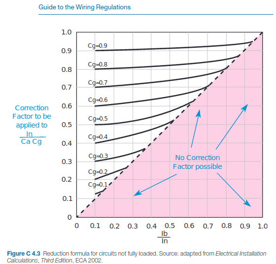
  • I think it will be a brave authority that sets that in print though there are things that come close This illustration comes to mind.

    lifted as an excerpt from here

    However what is left a bit open is how you decide that you are at say the 50% loading of Ib/In.

    If you think it only means steady loads - an exampe of 50% is a  16A heater on a 32A breaker, then nothing changes. If you think it means a 32A load for half the time say 10 mins on and ten mins off, them the shift is seismic !

    Firstly one has to decide how long one has to average the current over-  clearly more than a fuse blowing time, and less than 'all day' but the thermal time constant of cable is almost entirely determined by its environment - there are no tables for 'in running cold water' in the annex, but in practice the current rating is well over twice the free air rating - 4 times the heating power.

    For cables in walls, a waarm up/ cool down period of many tens of minutes may be about right.

    Then there is another problem, - the heat dissipated in a cable is proportional to the square of the current not just to the current so an 50% loading in current, is a 25% loading in terms of power.  - hence the rule of thumb that heating effects from anything carrying less than about a 3rd of its rated current can be ignored - it is dissipating less than  10% of the power it would be at full load.

    Then you have to decide what the loading will be in practice. and that need knowledge of the user - if the kettle cannot be on for more than 3 mins, as that is the time it takes to boil from cold. and only one person lives there, so only the kettle is used  once per meal, then the fact it shares a socket with the toaster, is not important - the 'both on' condition is time limited to a period short compared to the heat-up time.

    The same socket with 1 kettle and 1 toaster in a houseful of students all struggling to make coffee and toast before a nine-o'clock lecture will see a very different loading.

    (That's  maths physics and chemistry undergrads by the way, a house full of folk studying classics would not have that problem as those subjects are  less lecture based and more essays and assignments so there is not the same peak 'rush hour' effect. )

    A similar argument applies to machines in an amateur workshop with one user, who has got less than 3 hands, and is only doing one thing at  time,  and a business with lots of workers. so all the machines may be on and working hard at once.

    So the partial load thing is a minefield, and as far as I'm aware, all respectable authors shy away - which is a shame - after all,,we all know jump leads work for example, with cable that would normally be rated for tens of amps being hit my many hundreds but only for a few seconds but there is precious little design info out there for the equivalent wiring situation.

    Result, it's left to experience and the designer's personal appetite for risk - not the best place.

    Mike

  • 7.2.1 of the OSG goes partly there - giving rules of thumb that are around half as onerous as BS 7671 (1 cable dia spacing rather than 2 for example).

    Although my comment was based on the observation that I haven't seen a single CU in recent years that doesn't have some substantial grouping of the outgoing cables without any apparent increase in c.s.a.s or any evidence of overheating at that point. Nor have any of the EICRs I've seen ever commented on such an obvious non-compliance.

    If you work from the basis that the average load for a domestic (excluding long duration high current loads) is less than 2kW (probably closer to 1kW) - it follows pretty directly that many of the circuits must be carrying less than their 30% limit to be ignore anyway. For sure there will be some occasions where things will be overloaded (compared to their grouped rating) for a time - but cables don't instantly self destruct the moment they're overloaded, they just run a bit warmer and the overall life expectancy is reduced slightly - rather like the situation of using 20A cable on 32A ring finals with no actual controls where people can plug in 3kW fan heaters. I suggest it's another case of real world experience across millions of installations provides the empirical evidence that maths and general principles struggle to do.

       - Andy.

  • Afternoon Lyle,

    I got the 6mm dividing the In of 32a by Cg (0.73 , column 6 4C1) x Ca( 0.87 column 2 4B1)  to give an It of 50.38a, ( ref E table 4D2A ) although I see now both rating factors were incorrect but that's what started me on this path.

    Thanks for your time & help,

    Pete

  • Hello Andy,

    My 45 degrees was incorrect, I've taken advice from a collegue whose bolier is in a similar enviroment and never reaches even 35. I'm at sea level and one wall is single course brick to ext so poor insulation / good conduction. I also have width on the tray for appropriate spacing should an EV charger be added.

    Thanks for your time,

    Pete