Hello,
I have been looking for the "right" way to derive the following supply architecture at one of our sites:
- Supply A - LV
- Supply B - LV
- LV supplied feeds a LV main switchgear assembly in the main switchroom
- LV main switchgear has dual sections and a normally open bus coupler (N+1 sizing / run whole switchgear from one TX if needed)
- Downstream of the LV switchgear we connect sizeable UPS systems
- The UPS OEM has asked us NOT to switch the neutral (No 4 pole breakers) because their system is not designed for loss of N-E reference
NOTE: We own and operate our own HV and LV networks on our industrial sites (private supplies).
I have been trying to get my head round the requirements of the wiring regulations and have come up with the attached schematic:...
*EDIT* Picture replaced (hopefully more readable now)
I would appreciate peoples thoughts on:
- Have I missed anything that would be considered a no-no in BS 7671
- I am considering this a TN-S installation from the LV switchgears point of view
- Do people have any improvements or suggestions for the pole arrangements of the incomers and bus couplers?
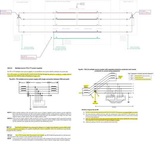
- I am not switching the neutral over (ref 463.1.4 compliance) but as we own Supply A and Supply B I am assuming this is permitted as per 551.6.2
- Have I interpreted this correctly
- Is the exemption for not switching the neutral discussed more explicitly elsewhere in BS 7671?
- Figure 9A note (b) "The function of this conductor is similar to a PEN" - Why so vague? Is this moot point?
- The TX's LV side are part of the electrical installation by BS 7671 definition
- This conductor is carrying neutral current and also acting as the connection to earth from the TX's "neutral" point of view
With the wiring regulations I sometimes struggle to see the wood for the all the trees!
Any feedback is gladly received
Thanks
