The IET is carrying out some important updates between 17-30 April and all of our websites will be view only. For more information, read this Announcement

Heat pump relay help ?

Hi guys after a bit of help please

We've been doing many heat pumps, samsung, Panasonic but our developer has now started to use Valiant.

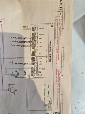
Its a arotherm set up and a bit different in it asks for a relay to supply the 24 volt side from the underfloor heat enable output. It mentions a DPDT relay. Not too sure how to wire this and also how a DPDT relay works.

Could anyone please help, wiring diagrams online were not clear. I attached a picture of the wiring diagram I have. Thank you

  •  I presume that is an extract of page 42 from here.
    If so it looks rather as if they expect the floor heating to have its own controls/ clock/ thermostat etc. that output "mains logic" voltage to operate the relay primary coil, while the Valient unit itself on connector S21 is just expecting contacts open/ close to turn the heat pump on. The relay, and as shown it could be single pole actually, is just doing the switch contact thing for you in response to the demand from the floor heating controls.

    You can verify this by temporarily wiring a light where the relay coil would go and a switch where the relay contact would go and pretending to be the relay.

    This is based on looking at the diagrams and a fair amount of assumption - I've not got the thing in front of me and that may not be your arrangement at all.

    I have seen quite a few heating controls where the control output exposes both sides of a floating contact, rather than making a wire live, and one of those would not really need the relay.
    Mike.

  • So the DPDT relay is shown at the bottom of the diagram you have posted (or right hand side if rotated). A DPDT relay has 2 sets of contacts (Double pole), which can each give 2 outputs (double throw), they will both operate at the same time but each can be considered separately. 

    The one in your drawing is only using one of the poles and is wired in a normally open configuration. The relay is acting as a volt-free contact for the EVU on the heatpump interface. With the control from the underfloor heating demand.

    So it is showing when the underfloor heating system calls for demand using which ever voltage it uses it will turn on the relay and activate the input on the heatpump interface.

    You would choose the voltage for the relay coil based on what voltage the underfloor heating system demand is using.

    If the underfloor heating system has a volt-free contact you could go directly to that instead of a relay.

  • Hiya yes really not sure on this relay side

    I assume its a 240 supply to the coil a1 a2 and then 24 volt out ?

  • Yes it will have a 240 volt out heat enable but the heat pump controls require 24 volts so the relay is to drop that voltage down

  • So if demand is using 240, that will be the coil voltage. The heatpump interface itself will provide its own voltage to go around the EVU loop as shown in your diagram. 

    The only other consideration would be if there is a distance limitation on the EVU loop for the location of the relay, but that should be in the documentation.

  • Does this mean I take live neutral to a1 and a2 as when I done this it tripped

    The wholesalers supplied me with a certain relay a repol gsz80 

  • Essentially, but your live will be coming from what is controlling the heating demand, either from a thermostat or from the underfloor heating control, so it will become a switched live, and the neutral is neutral.

    So it would work in the same way a room thermostat would take live in, then give a switched live out to go to the heating device to turn it on. In your case it is turning on the relay.

    If you wire the relay A1,A2 straight to live and neutral the relay will turn straight on as there is nothing to control the feed to the relay.

  • The live to the relay is the switch live from the heat enable on the underfloor heating manifold. 

    I wonder what caused it to trip then ? It blew on the relay

    The two cables then going on the output side I wired into common and a normally open terminal. Is the relay is mentioned suitable?

  • So the part you mentioned is actually the plug in relay base "gzs80". Having a look on RS components, it looks like the relay itself would have a part number format like this "RM84-2012-35-5230", so double check the relay itself, mainly the coil voltage is correct.

  • Thank you I will check that tomorrow