Upstream protection for short circuit current

We are providing some lighting dimmer panels (they also provide hard power and switched power - configurable on a per-channel basis) for a theatre installation.  All the dimmer outputs are 10A single phase circuits and the dimmer has a 3-phase supply.

The electrical consultant has stated that the worst case PFC for a fault at the dimmer outputs is approx 9kA - presumably this is on a bolted phase-phase short..  The dimmers are provided with 6kA breaking capacity Type C 10A MCBs (to EN 60898) with neutral disconnect for their output circuits. The consultant is saying that these must be replaced with 10kA devices.  This of course is not a simple matter as the product is CE/UKCA marked and such a modification would likely require a re-certification by the manufacturer with significant cost and time impacts.  Clearly we can't simply swap the devices over ourselves and the manufacturers are not keen to do it either.

The upstream protective device is a 80A Type D MCB to EN60947-2 (fixed - non adjustable), and has a breaking capacity of 10kA. Looking at the trip time curve for that device once you get to around 800A you hit the 'instantaneous' region.  Likewise for the dimmer MCB once you hit 100A you are in the 'instantaneous' region.

My argument is that if there If there is a fault current of 1kA-6kA, you're likely to be in to a race between the 80A and 10A breakers where you can't predict the winner anyway, and in the worst case of a fault current >6kA and the 10A MCB welds shut the 80A MCB will open within it's fastest possible operation anyway (sub 0.1s).

Also, on a 4mm2 CSA output cable by my calculations once you get to about 8m of cable the worst case fault current is dropped to 6kA anyway.

434.5.1 provides for a higher breaking capacity device upstream to provide protection for a downstream device, although energy let-through needs to be considered.

Is my logic correct or flawed, and is there anything else we would need to do to determine if the configuration decsribed above is compliant?  We know the very high fault current would be an edge-case in terms of likelihood but the electrical consultant is very particular on this project.

NB - We have looked at alternative manufacturers of similar products (there aren't many) and they all use 6kA MCBs.  There is a 'bigger brother' product with higher breaking capacity which won't fit physically and would have a significant cost uplift that I expect will not be feasible.

Thanks in advance.

Jason.

Parents
  • This of course is not a simple matter as the product is CE/UKCA marked and such a modification would likely require a re-certification by the manufacturer with significant cost and time impacts.

    Why do you need a CE marking? My understanding is that a CE marking is required to be applied by the manufacturer when selling a product within the EU/UK. I'm not aware of any requirement for the user to install only CE marked products - although I'm happy to be corrected.

  • if the circuit-breakers were changed from 6kA to 10kA, could it not be argued that the equipment still complies with the relevant standards?

    Depends on the design of the equipment. Higher rated circuit breakers tend to have larger energy let-though (bigger chunkier construction, so more mass to get moving to open contacts, so slightly slower action) - so in some cases what was adequately protected before may not be afterwards.

      - Andy.

  • so in some cases what was adequately protected before may not be afterwards.

    Agreed ... as per examples above.

  • It would not necessarily render the installation non-conformant, but yes the manufacturer might not want to take responsibility for the equipment thereafter.

    However, it MIGHT render the installation non-conformant with BS 7671, and become a breach of the Electricity at Work Regulations.

    If you change the breaker for another one, will the semiconductors and PCB tracks remain protected against damage ... and possible fire or other damaging event ... in a short-circuit ?

    This type of issue would be a case of exceeding the ratings, or 'strength and capability', of electrical equipment.

    So, if that were to be the case, possible non-conformity with BS 7671 (Regulations 131.3 and 131.4) and possibly a breach of  Regulation 5 and/or Regulation 11 of the Electricity at Work Regulations 1989.

  • We are in discussion with the manufacturer of the dimmer units about this and they have raised the same issue that they would need to review the entire product if the breaking capacity of the outgoing MCBs were to be increased.  Presumably they have designed and tested  it to be able to withstand fault currents of up to 6kA and the associated energy let-through of their selected protective devices.  I have enquired as to the 'internal resistance' of the unit (as referenced by Mike above) as if that alone would reduce the PSCC at the outputs to below 6kA then it could be OK.  By my very rough maths around 12 milliOhm would be sufficient - and if the worst case is a phase-phase short then that would require a path through 2 different channels on the panel, so 6mOhm each could be enough.

  • if the breaking capacity of the outgoing MCBs were to be increased.  Presumably they have designed and tested  it to be able to withstand fault currents of up to 6kA and the associated energy let-through of their selected protective devices.

    Do you have the make and model details of the circuit-breakers currently installed? There might be a 10kA device available with a lower energy let-through?

  • The dimmers are ETC Colorsource Thrupower units: Link

    They use a Noark MCB (I haven't heard of them either) as their protective device on the outputs: Link

    You raise an interesting point.  ETC as the manufacturer would still need to validate a modification but that may be easier if a 10kA device has a lower energy let-through. There is a Schneider Aciti9 10kA device that looks like it would fit.  Energy let-through/withstand data is not easy to come by with all manufacturers but we could try. 

    We could also look at the upstream fuse suggestion as well.

    These are not yet installed, but they are procured and in our warehouse due to long contract periods and wanting to preserve the purchase price (client decision).

  • Hi jb, how does this consultants opinion fit into the contract? 

  • Not a simple answer to that one.  We are contracted as a specialist sound and lighting contractor to a main contractor.  A Theatre Consultant specified the dimmer panels and named the ETC product as approved - although we had the freedom to choose another if we wished. The electrical consultant is employed by the end client (venue owner) to serve as the electrical designer - I presume it will be their name in the 'design' box on the certificate.  There is an electrical contractor also employed by the main contractor.  We free-issue the dimmer panels to them for installation and testing of the electrical installation (their names in those boxes).

  • CE marking does not guarantee electrical safety. It shows it meets the standards the makers declare they tested it to, nothing more or less. If they don't mention a supply PSSC, they won't have considered it at all.
    Installers can in general., and do, install what and how they like.

    Mike,

  • I was wondering the same. In the product data sheet of the dimmer panel link it doesn't make any mention of a maximum short-circuit current. The standards listed are:

    EN61439-1, EN55015, EN61000-6-1, EN61000-6-2, ESTA DMX512-A/RDM.

    Doesn't the manufacturer have to give the Icw or Icc per 61439?

Reply
  • I was wondering the same. In the product data sheet of the dimmer panel link it doesn't make any mention of a maximum short-circuit current. The standards listed are:

    EN61439-1, EN55015, EN61000-6-1, EN61000-6-2, ESTA DMX512-A/RDM.

    Doesn't the manufacturer have to give the Icw or Icc per 61439?

Children
  • only if they, (the manufacturer) think (well declare) that that specific standard applies.  Generally CE marking law does not form a complete set, even if folk are trying to follow it at all.
    Mike.

  • I was wondering the same. In the product data sheet of the dimmer panel link it doesn't make any mention of a maximum short-circuit current. The standards listed are:

    EN61439-1, EN55015, EN61000-6-1, EN61000-6-2, ESTA DMX512-A/RDM.

    Doesn't the manufacturer have to give the Icw or Icc per 61439?

    Yes, Clause 6.2.1 of EN 61439-1 requires defined parameters of Clause 5 of the standard, including Icw and Icc, to be provided in technical information provided with the assembly ... for conditional short-circuit current, information on selection of an appropriate short-circuit protective device is also required.

  • ICC is given in the Installation Manual as 6kA - unsurprising given the breaking capacity of the MCB's they use.  I have asked them for an energy withstand figure as the current figure on it's own is not the full picture.  That might give us a clue as to if the upstream protection may be adequate, or if we added tome BS88 fuses upstream that may sufficiently limit the energy let-through to a value that the dimmer way withstand.

  • ICC is given in the Installation Manual as 6kA - unsurprising given the breaking capacity of the MCB's they use.  I have asked them for an energy withstand figure as the current figure on it's own is not the full picture.  That might give us a clue as to if the upstream protection may be adequate, or if we added tome BS88 fuses upstream that may sufficiently limit the energy let-through to a value that the dimmer way withstand.

    I wasn't sure that makes 100 % sense ... and it doesn't, because Icc is not quoted.

    Instead, Icw is quoted, along with Ipk, both at 6 kA, which, unless the manufacturer provides further information (a value for Icc and a related OCPD specification) means there's no 'conditional rating' actually quoted in the manual, against which an upstream OCPD could be specified.

    Explanation ... Icc (where specified) is a conditional short-circuit rating, usually higher than Icw and to achieve that rating an upstream short-circuit protective device, as specified by the manufacturer, is required for installations in which the prospective short-circuit current exceeds Icw.

  • Sorry - my error in the subscript there.

    Thanks for the explanation - very helpful as this is deeper into this subject than I have gone before.

    If I interpret your post correctly, the manufacturer can provide an ICC along with a condition (or set of conditions) that must be met for that rating to apply - e.g. an upstream OCPD specification.  Might that include for example a maximum energy let-through figure for the upstream device?

    I'll follow that up with the manufacturer (along with the request for the 'internal resistance' value or the dimmer) and see where I get to.

    Any other innovative solutions to this problem welcomed!

  • If I interpret your post correctly, the manufacturer can provide an ICC along with a condition (or set of conditions) that must be met for that rating to apply - e.g. an upstream OCPD specification.  Might that include for example a maximum energy let-through figure for the upstream device?

    Yes, or say a particular specification (standard, rating and type) of fuse etc.

    (along with the request for the 'internal resistance' value or the dimmer)

    I did have a thought about this ... and decided it's probably not worth pursuing, because if the fault occurs inside the dimmer, only part of, or perhaps little or none of, the internal resistance might be included in the short-circuit path, but we still would want to be happy the dimmer didn't set on fire or cause other hazards.

    I can see where the suggestion came from, but with short-circuit current calculations in BS 7671 ('adiabatic') we consider a fault anywhere on the circuit. More traditionally, when a single fuse is used for a circuit, the "worst case" would be at the far end of the circuit (or a check at each end might do the trick) ... but with circuit breakers, or "combined protection" (two protective devices), things get more tricky, and the worst-case might be at the supply end of the circuit.

  • Yes - the internal resistance concept was originally based around the expressed concern that the MCB's, which are normally at the output, are only rated at 6kA and the PFC may be 9kA.  For that specific issue, the internal resistance would be in play, but your point about the assessment 'through the product' definitely widens the scope of that discussion. 

    At the input to the dimmer, the wiring is protected by a 10kA rated device and I'm assuming the consultant has done his adiabatic correctly for that bit of the circuit, but the 'internal analysis' through the dimmer could be much more complex and would rely on the manufacturer.

    If we don't get to an engineered and accepted solution the alternatives are not great for the project.  There is a 'bigger brother' ETC product with a much larger form factor that likely won't fit in the room and will have significant cost impact for the project.

  • yes, but in self certification route,  the design authority have to decide first which standards and secondly which bits of which standards are actually applicable to their case. Almost no-one uses the notified body route, so no-one external is marking the homework before going to market as it were, and the correct answer is not 'test everything' that is impossible to pass with conflicting requirements.

    Being responsible for getting a product through CE marking can actually become incredibly stressful, as there is a serious risk of missing stuff that others may later decide is relevant or of failing something due to a test that actually should not have been considered relevant. It is  something I have occasionally had to do, and I don't like it.

    There are a lot of occasions when you see  stuff that seems to be sold  with a CE mark  certificate and a rather 'oh sod it' short list of tests that may be deliberate, or just a limitation of the folk doing it.

    Mike

  • "because if the fault occurs inside the dimmer, only part of, or perhaps little or none of, the internal resistance might be included in the short-circuit path, but we still would want to be happy the dimmer didn't set on fire or cause other hazards."

    Yes, bur given its a steel box, one can very quickly set a very high bar, to the total liberated energy permissible, as all that is required is to contain the arc so the flash does not set fire to the curtains, and to catch all the flying bits  - nothing has to survive to work again, as by then it is a repair job anyway.

    It may be informative to consider that more in the manner of a blast calculation.

    Thinks like cheaper laptop power supplies use PCB track as open fuses for example, because the containment means it is fine.

    Mike.

  • Noark are well were,  a North American company, but part of the Chint group,  and generally their European 240V 50Hz  product line is the same as their 277V 60Hz measured against a different set of tests.

    Without knowing the exact breaker part no, this may be about right - 'US web data for noark Din Rail breakers

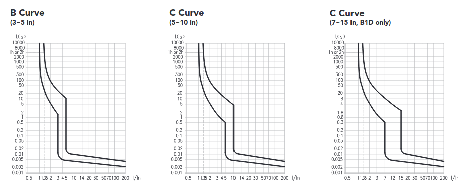
    Unlike much European data, they give curves that go far enough into overload to really show the time limiting of the mechanism. For the 'C' type, a factor of 20 in current gets you from about 10msec to about 5msec.

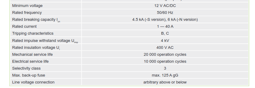
    Edit readng back up the thread, and now knowning the part no (oops) here is the datashet

    one sees the 6kA is an ICN (so will break, may not survive) and then further down the line

    "max back-up fuse 125A gG" so there is already a reliance on upstream time / energy limiting to achieve the 6kA level.

    Mike.